SB-301 / SB-401 Station · Volume 3
Transceive
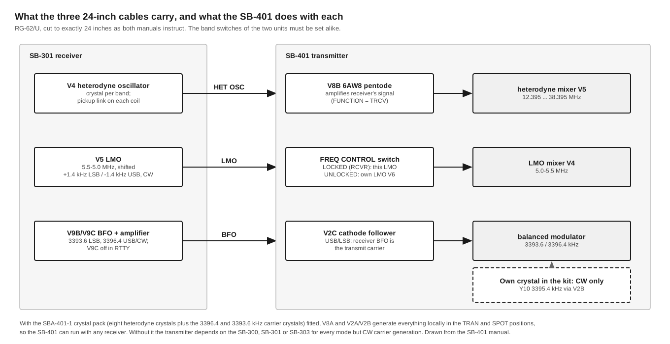
A modern reader might expect “transceive” to mean that the transmitter follows the receiver’s dial through some kind of control link. On the SB-301 and SB-401 it is more direct than that. The receiver’s own heterodyne crystal oscillator, its LMO and its BFO are wired out to the transmitter, and the transmitter uses those signals to build its output. In transceive the SB-401 has no heterodyne crystals, no sideband carrier crystals and no active LMO of its own. It is not synchronised to the receiver. It uses the receiver’s oscillators, so the two units cannot be on different frequencies unless the operator switches them apart.
This volume explains which signals travel, what the transmitter does with each, why a CW carrier crystal is still needed, and how the arrangement changed between the SB-400 and SB-401 and again for the SB-303.
3.1 Why the sharing works
How It Works gives the arithmetic. Here it is in one line. The receiver turns a signal at f into the IF by computing crystal − f − LMO. The transmitter turns a sideband at the IF into an output at f by computing crystal − (IF + LMO). These are the same equation rearranged. If both units use the same crystal frequency and the same LMO frequency, the frequency the receiver is tuned to and the frequency the transmitter puts out are identical by construction. No two oscillators have to be matched, and no drift between them is possible. If the LMO drifts, the receiver and transmitter drift together.
The carrier is handled the same way. A transmitted SSB signal sits correctly only if its suppressed carrier falls where the receiving product detector’s BFO expects it. Heath’s 1966 catalogue made the point for the SB-300 and SB-400: “Use of a common BFO crystal in transceive operation prevents even the most minute frequency difference” (1966 catalogue, SB-300 page). In transceive on SSB the SB-401’s carrier is the SB-301’s BFO. It arrives at the RCVR BFO jack and goes through V2C to the balanced modulator. The transmitter’s own LSB and USB oscillators are not powered.
3.2 The cables
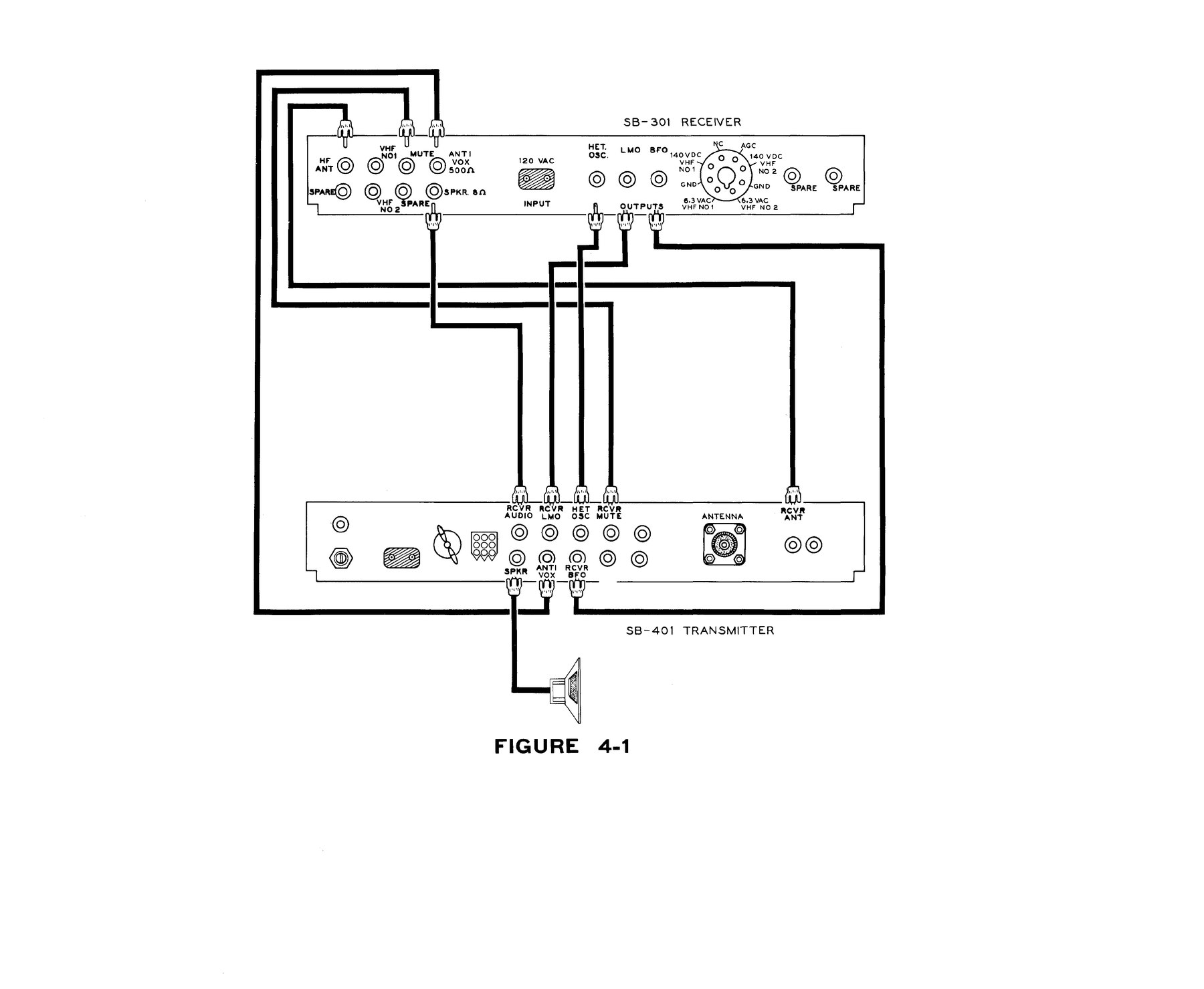
The SB-301 has three output jacks on the right-hand end of its rear apron, marked HET. OSC., LMO and BFO. The SB-401 has matching inputs: HET OSC, RCVR LMO and RCVR BFO. Both manuals specify the interconnecting cables precisely: RG-62/U coax, supplied with the receiver kit, cut to exactly 24 inches (SB-301 manual, p. 73; SB-401 manual, Figure 4-1B). W2JDL’s 1967 review made the same point (73, July 1967).
Neither manual explains the insistence on length. The likely reason is that the cables are part of the loading on the oscillator outputs. The heterodyne signal is taken from small pickup links on the receiver’s tuned oscillator coils, and a length of RG-62/U adds a fixed, known capacitance to that load. The SB-401 manual’s note for the SB-303 supports this. It warns that the receiver’s heterodyne-oscillator coils may need re-peaking “due to the loading by the Transmitter heterodyne oscillator circuit”, with the transmitter connected but not even switched on (SB-401 manual, p. 109). A cable of a different length would change that loading and upset the alignment. This explanation is an inference, not a statement from Heath.
The same manual gives the one adjustment the receiver needs for transceive. With the cables connected, an RF probe goes on the centre pin of the transmitter’s BFO jack, and the receiver’s BFO output coil, L20, is peaked. The manual says to expect about 5 volts.
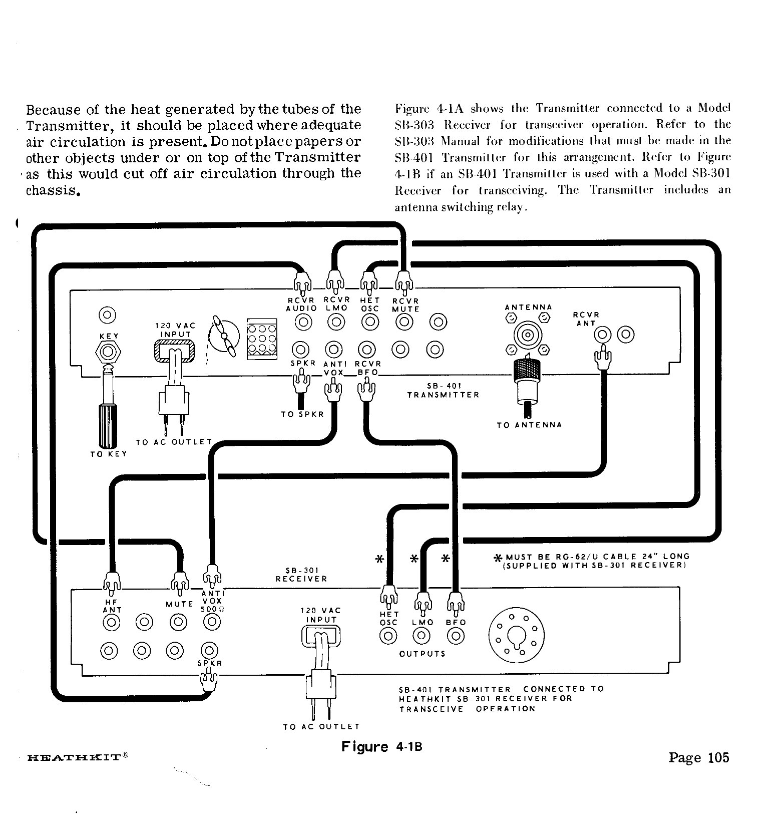
The station needs four more connections, none of which carry oscillator signals:
Table 1 — The station needs four more connections, none of which carry oscillator signals
| From | To | Purpose |
|---|---|---|
| SB-401 RCVR ANT | SB-301 HF ANT | The transmitter’s internal relay switches the antenna to the receiver during receive |
| SB-401 RCVR MUTE | SB-301 MUTE | The relay opens this line on transmit; the receiver, in STBY, cuts off its RF, mixer, IF and audio stages |
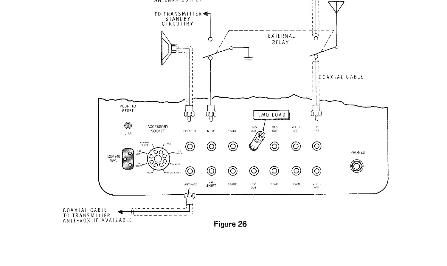
| SB-301 ANTI-VOX 500 Ω | SB-401 ANTI-VOX | Receiver audio cancels itself in the VOX circuit so the speaker cannot key the transmitter |
| SB-301 SPKR 8 Ω → SB-401 RCVR AUDIO; SB-401 SPKR → speaker | The relay switches the speaker from receiver audio to the CW sidetone on transmit |
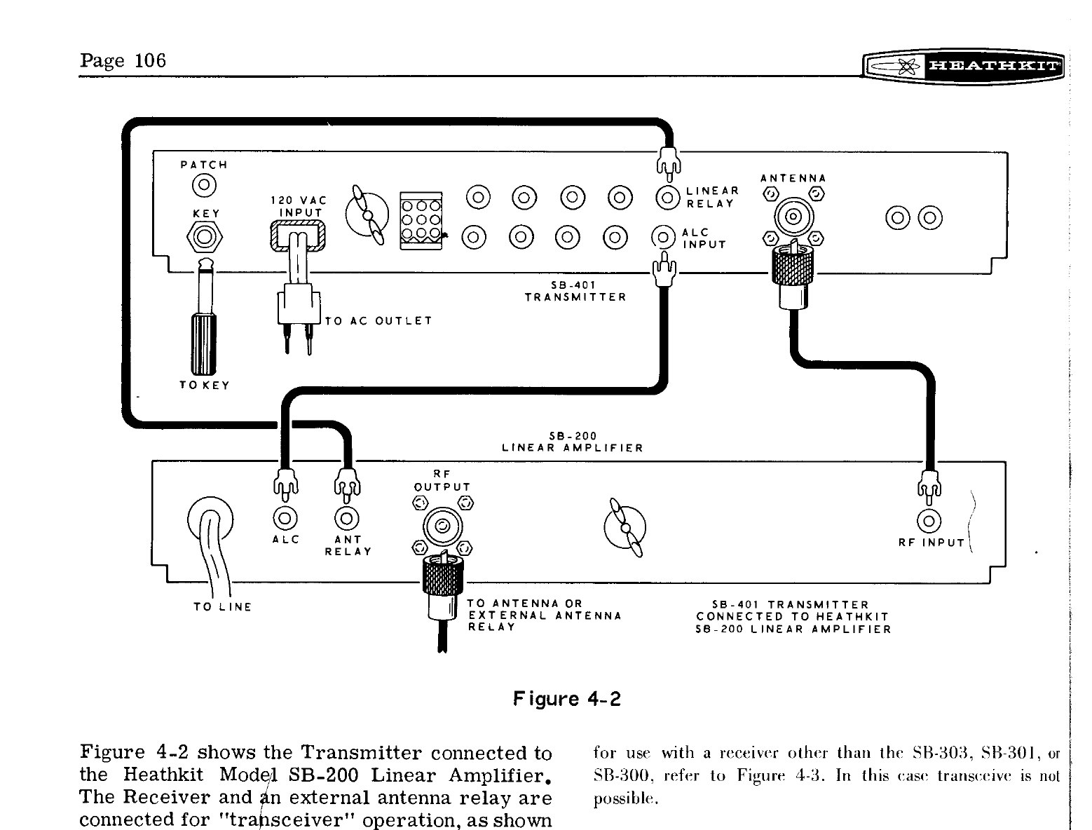
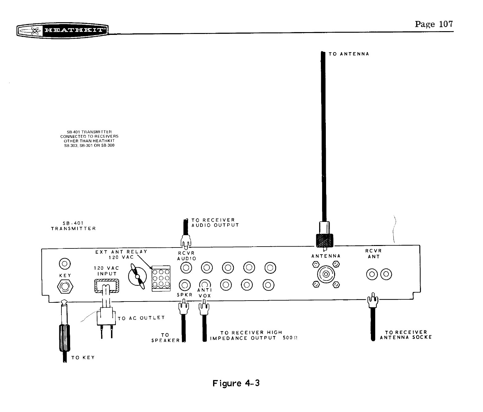
The receiver’s FUNCTION switch must be in STBY for the mute line to work. In OPR the receiver grounds the line itself, so the station would receive its own transmission at full gain.
3.3 The switches
Two controls on the SB-401 decide where each signal comes from.
The FUNCTION switch has five positions: OFF, STBY, TRCV, TRAN and SPOT. In TRCV, B+ goes to V8B, the pentode that amplifies the receiver’s heterodyne signal, and not to V8A, the transmitter’s own crystal oscillator. In TRAN and SPOT the reverse happens, which only works if the SBA-401-1 crystals are fitted.
The FREQ CONTROL switch, concentric with the MIC/CW LEVEL knob, has two positions. LOCKED (RCVR) routes the receiver’s LMO to the transmitter’s LMO mixer, so the transmitter goes wherever the receiver’s dial goes. UNLOCKED routes the transmitter’s own LMO there instead.
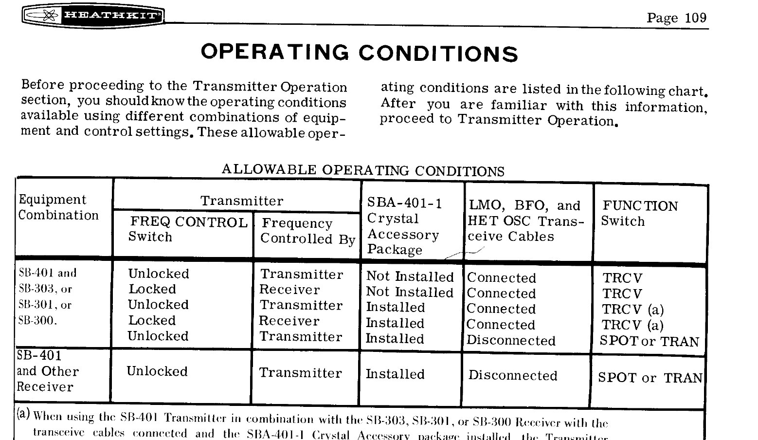
The SB-401 manual summarises the legal combinations in a chart:
Table 2 — The SB-401 manual summarises the legal combinations in a chart
| Equipment | FREQ CONTROL | Frequency set by | SBA-401-1 crystals | Oscillator cables | FUNCTION |
|---|---|---|---|---|---|
| SB-401 with SB-300, SB-301 or SB-303 | UNLOCKED | Transmitter | Not installed | Connected | TRCV |
| LOCKED | Receiver | Not installed | Connected | TRCV | |
| UNLOCKED | Transmitter | Installed | Connected | TRCV (a) | |
| LOCKED | Receiver | Installed | Connected | TRCV (a) | |
| UNLOCKED | Transmitter | Installed | Disconnected | SPOT or TRAN | |
| SB-401 with any other receiver | UNLOCKED | Transmitter | Installed | Disconnected | SPOT or TRAN |
Note (a) in the manual: with the cables connected and the crystal pack fitted, the FUNCTION switch must stay at STBY or TRCV, “otherwise a steady tone will be heard in the Receiver” (SB-401 manual, p. 109).
That footnote records a problem found in the field. W2JDL, reviewing the SB-401 in 1967, discovered that with the pair cabled together for CW, setting the transmitter to TRAN instead of TRCV produced a constant beat note in the receiver. He wrote that this “isn’t too clear in the manual and it took a personal discussion with the Heath engineers before it was cleared up”. Heath then issued a bulletin and revised current production, “This also applies to the SB300/400 combination” (73, July 1967). The rule that came out of it is simple. With the oscillator cables connected, the SB-401 stays in TRCV whether the pair is transceiving or working split.
The second row of the chart describes a mode the SB-400 could not offer without opening the cabinet: split operation without the crystal pack. In UNLOCKED the transmitter’s own LMO sets the transmit frequency. The heterodyne signal and the SSB carrier still come from the receiver, so the transmitter stays in the receiver’s 500 kHz band segment but can be anywhere within it. That was all a DX operator needed to call a station listening a few kilohertz up. Two limits follow from how it works. Both band switches must always be set alike, and transmitting on a different band from the one being received needs the SBA-401-1 crystals.
3.4 CW: why the transmitter keeps one crystal
On SSB the receiver’s BFO serves as the transmit carrier, but on CW it cannot. The receiver’s CW position uses the same BFO crystal as USB, 3396.4 kHz, and the CW filter is centred 1 kHz below it at 3395.4 kHz. A CW signal centred in the filter therefore produces a 1 kHz tone. If the transmitter keyed a carrier at the BFO frequency, its signal would come out 1 kHz away from the station being answered.
So the SB-401 generates its CW carrier at 3395.4 kHz from its own crystal, Y10, supplied with the kit. The transmitter’s crystal matches the centre of the receiver’s CW filter, not its BFO. Worked through at a dial reading of 28.375 MHz with the LMO in its USB/CW position (5,123.6 kHz):
Table 3 — So the SB-401 generates its CW carrier at 3395.4 kHz from its own crystal, Y10, supplied with the kit. The transmitter's crystal matches the centre of the receiver's CW filter, not its BFO. Worked through at a dial reading of 28.375 MHz with the LMO in its USB/CW position (5,123.6 kHz)
| Receiver | Transmitter | |
|---|---|---|
| Station heard (or signal sent) | 28,376.0 kHz | 28,376.0 kHz |
| Heterodyne crystal | 36,895.0 kHz | 36,895.0 kHz (from the receiver) |
| First IF / bandpass coupler | 36,895.0 − 28,376.0 = 8,519.0 | 3,395.4 + 5,123.6 = 8,519.0 |
| LMO | 5,123.6 | 5,123.6 (from the receiver) |
| Second IF / carrier | 8,519.0 − 5,123.6 = 3,395.4 (centre of CW filter) | 3,395.4 (Y10) |
| Result | 3,396.4 − 3,395.4 = 1,000 Hz tone | 36,895.0 − 8,519.0 = 28,376.0 kHz |
The frequencies follow Eckweiler’s tables for the SB-301 and SB-401 (HOTM #36; HOTM #43). A station heard as a 1 kHz note in the CW filter is answered exactly on its own frequency, and the transmitted signal reads 1 kHz higher than the dial. Heath’s own wording reverses the direction. The circuit description says the receiver is tuned 1 kHz above the station and that “the transmitter CW carrier generator automatically compensates and transmits a signal 1000 Hz below the receiver dial setting” (SB-401 manual, p. 129). The operating instructions likewise say to set the dial “1 kHz higher than the zero beat”. Working the arithmetic with the published crystal frequencies, and with the LMO in its USB/CW position, gives the result in the table: the dial reads 1 kHz below the station and the transmitter, which is also Eckweiler’s reading. The manual’s sign may assume a different reference for “zero beat”, or it may simply be an error. This dive could not settle which. In practice it makes no difference, because the design puts the received and transmitted signals on the same frequency either way. Tune the other station to a 1 kHz note in the CW filter and reply.
The SB-301 manual adds one practical tip. The CW filter is too narrow to hear zero beat, so a CW signal is best found in the USB position and tuned to a 1 kHz note, then the mode switch is moved to CW for single-signal reception (SB-301 manual, p. 76).
3.5 What cannot be transceived
- RTTY. The receiver’s BFO amplifier, V9C, is switched off in the RTTY position “to prevent accidental transceiving”. The RTTY BFO crystal (3392.110 kHz) would put a transmitted signal in the wrong place, and the audio passband is wrong for voice.
- AM and CAL. The SB-401 manual cautions: “Do not attempt to transceive with the Receiver in the AM or CAL modes, as the units will not function properly”. The SB-401 has no AM mode, and in AM the receiver’s BFO is off.
- Different bands. Without the crystal pack the transmitter can only use the heterodyne crystal the receiver has selected.
3.6 From SB-400 to SB-401
The SB-400 could already transceive with the SB-300, and it came with every crystal. Changing between transceive and independent operation was awkward. Dave Kechkaylo, W8QIZ, described it on the Heath mailing list: the owner had to “install an LMO jumper under the hood”, remove coaxial connections between boards, and on SSB “pull the BFO plug” to stop the two carrier oscillators interfering (heath list, 25 March 2002). Eckweiler describes the same job as “raising the cabinet top and changing a coaxial jumper link” (HOTM #43). The SB-401 replaced all of that with the FREQ CONTROL switch.
Its marketing idea mattered as much as the switch. Heath noticed that most SB-400s were being used with SB-300s, which already contained the heterodyne and carrier oscillators. So the SB-401 kit dropped the transmitter’s own set of eight heterodyne crystals and two sideband crystals and sold them separately as the SBA-401-1 crystal pack for $29.95. The kit price fell by $40 (catalogue 810/67A, p. 83). The pack contains:
Table 4 — Its marketing idea mattered as much as the switch. Heath noticed that most SB-400s were being used with SB-300s, which already contained the heterodyne and carrier oscillators. So the SB-401 kit dropped the transmitter's own set of eight heterodyne crystals and two sideband crystals and sold them separately as the SBA-401-1 crystal pack for $29.95. The kit price fell by $40 ([catalogue 810/67A, p. 83](https://www.worldradiohistory.com/Archive-Catalogs/Allied-Catalogs/Heathkit-1967.pdf)). The pack contains
| Crystal | Frequency (kHz) | Use |
|---|---|---|
| Y1–Y4 | 38,395.0, 37,895.0, 37,395.0, 36,895.0 | 29.5, 29.0, 28.5, 28.0 MHz segments |
| Y5 | 29,895.0 | 21.0 MHz |
| Y6 | 22,895.0 | 14.0 MHz |
| Y7 | 15,895.0 | 7.0 MHz |
| Y8 | 12,395.0 | 3.5 MHz |
| Y9 | 3,396.4 | USB carrier |
| Y11 | 3,393.6 | LSB carrier |
| Y10 (in the kit) | 3,395.4 | CW carrier |
The table follows Eckweiler, HOTM #43, table 1. W2JDL summed it up for the reader who already owned the receiver: “you can buy the transmitter for less without the crystals”. Eckweiler used his SB-401 with an SB-301 for more than 25 years, worked DXCC with it in both transceive and split, and never installed the crystal pack.
3.7 With the SB-303
The solid-state SB-303 kept the three oscillator jacks, renamed LMO OUT, BFO OUT and HFO OUT, so the SB-401 could transceive with it. The electrical interface was different, and the SB-303 manual includes a transmitter modification kit in the receiver’s parts: two 68 Ω resistors and one 270 Ω resistor (SB-303 manual, Installation). For an SB-401 the steps are:
- On the FREQ CONTROL switch, remove the 100 Ω resistor. Fit a 68 Ω resistor from lug 6 to the control’s solder lug and another from lug 4.
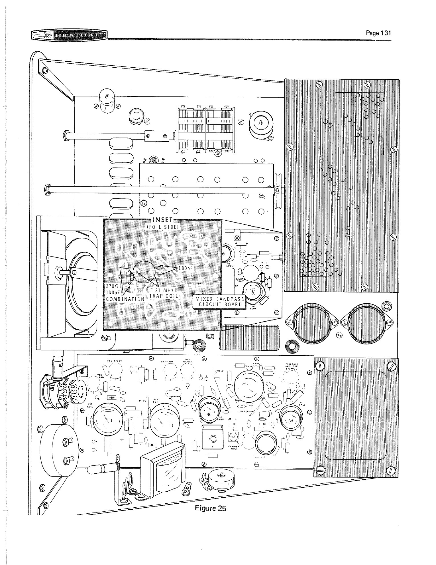
- On the mixer-bandpass board (85-154), take out the 6EW6 LMO mixer. Remove the 21 MHz trap coil (40-479) and a 180 pF capacitor. Replace a 270 Ω and 100 pF combination with a plain 270 Ω resistor.
An SB-400 needs only a 68 Ω resistor across its RCVR LMO jack. For the SB-303 the cables are RG-174/U, again 24 inches long. The manual does not explain the resistors, but 68 Ω across the LMO input and output reads as a termination suited to the SB-303’s low-impedance emitter-follower outputs. The high-impedance tube inputs of the SB-401 were designed for the SB-301’s tube outputs. That is an interpretation, not Heath’s wording. Later printings of the SB-401 manual were rewritten around the SB-303. Their main alignment procedure is titled “Alignment with SB-303 Receiver as a Transceiver”, and they refer the SB-401 owner to the SB-303 manual for these changes.
Heath returned to the pairing in 1974. Service bulletins SB-401-3 and SB-401-4, both dated 23 May 1974, set out an alignment procedure for an SB-301 and SB-401 used together. It includes moving crystals between the units and setting the receiver’s BFO coil by measuring the voltage at C127. The bulletins also cure feedback and zero-beat trouble by rerouting the red antenna lead away from the final amplifier, or replacing it with coax (Lutz, SB-401 bulletin index). W5RKL hosts a later document on the same subject for the solid-state pairing, “SB303 and SB401 Transceive adjustments” (W5RKL).
Sources
- Heath Company. Assembly Manual, SSB Receiver Model SB-301, 595-946-01, Installation and Operation, pp. 73–76. W5RKL scan
- Heath Company. Assembly and Operation of the SSB Transmitter Model SB-401, Installation and Operation, pp. 105–116; Circuit Description, pp. 129–133. Internet Archive
- Heath Company. Assembly Manual, Solid-State SSB Receiver Model SB-303, 595-1124, Installation. Internet Archive
- Heathkit catalogues: 1966 · 810/67A
- Eckweiler, Bob, AF6C. “Heathkit of the Month #36: SB-301”, rev. A. PDF; “#43: SB-401”. PDF
- Waters, Mort, W2JDL. “The Heathkit SB401 Transmitter.” 73 Magazine, July 1967. Internet Archive
- Kechkaylo, Dave, W8QIZ. Reply on SB-400 and SB-401 differences, heath mailing list, 25 March 2002. Archive
- Lutz, Joseph W. “Heathkit Service Bulletins: SB-401 (Complete 1966-89).” heath mailing list, 13 June 1998. Archive
- W5RKL. “SB303 and SB401 Transceive adjustments.” PDF
Comments (0)