SB-104A Transceiver · Volume 2
How It Works
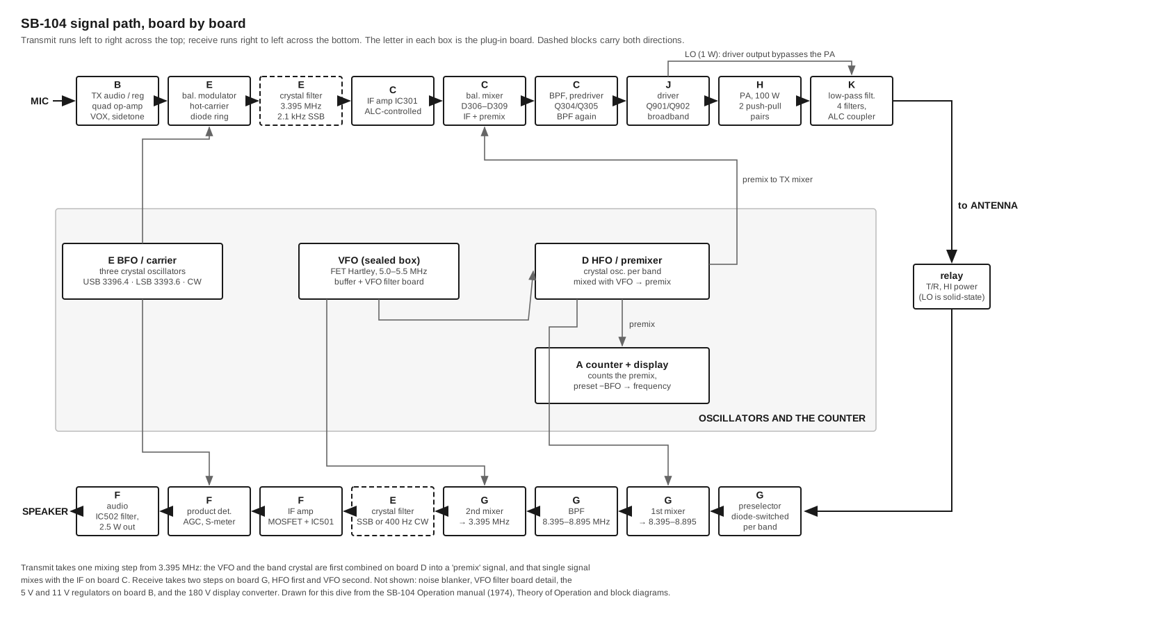
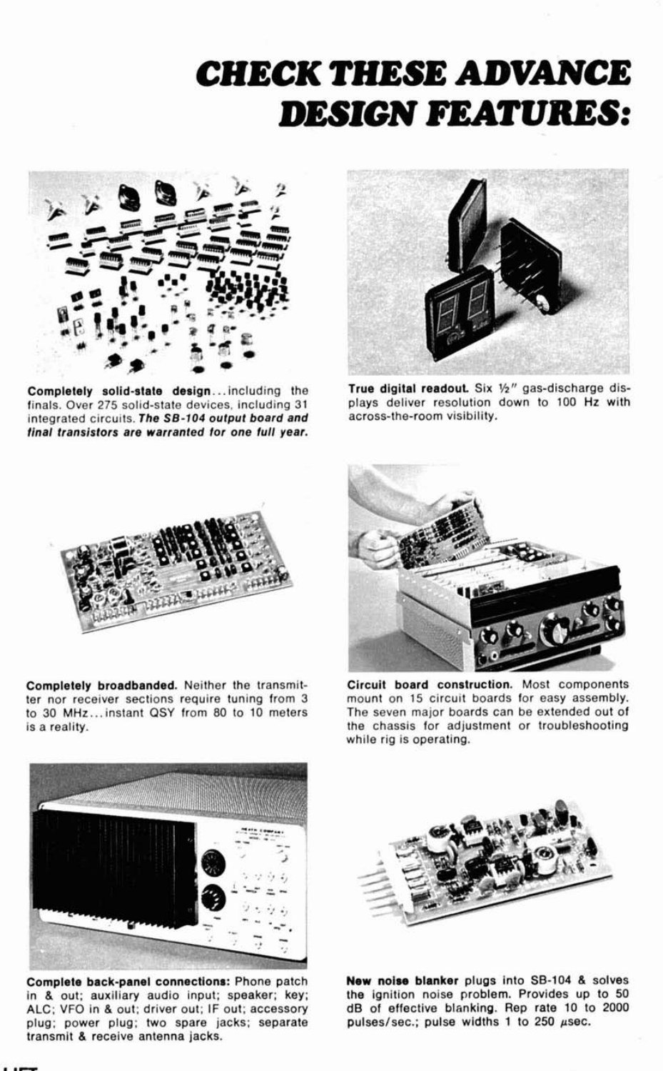
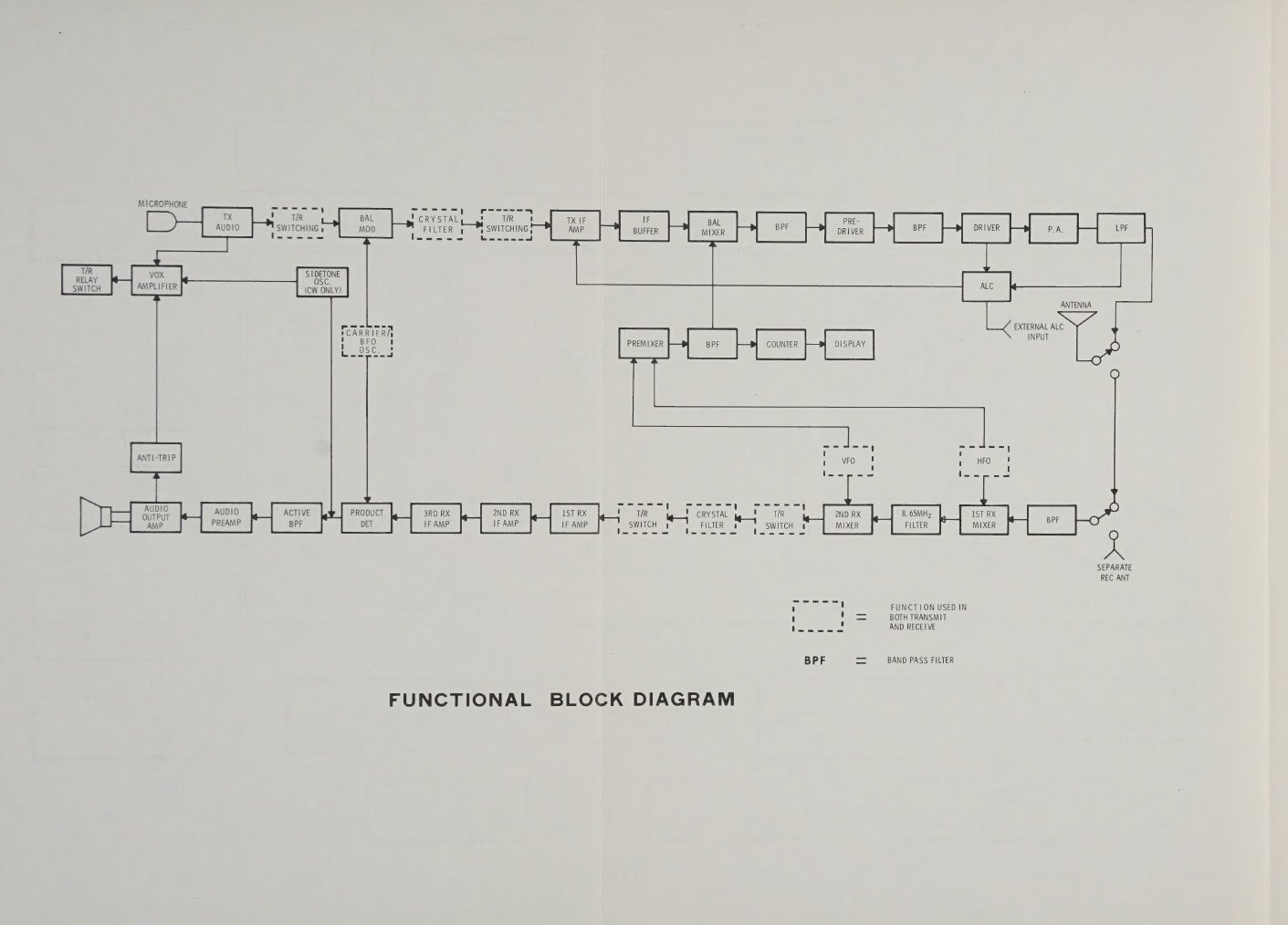
On paper the SB-104 is the same radio as the SB-102 it replaced. It is a filter-type single-sideband transceiver with a crystal filter at 3.395 MHz, a VFO tuning 5.0 to 5.5 MHz, and one crystal per band to carry the signal to and from the operating frequency. The frequency plan and even the filter part were inherited. The execution is new throughout. Tubes became transistors and integrated circuits. Rotary band-switch wafers became diodes switched by DC voltages. Tuned driver and final tanks became broadband transformers and a set of low-pass filters. A dial became a counter. This volume works through the rig board by board, in the order a signal meets them.
2.1 The board map
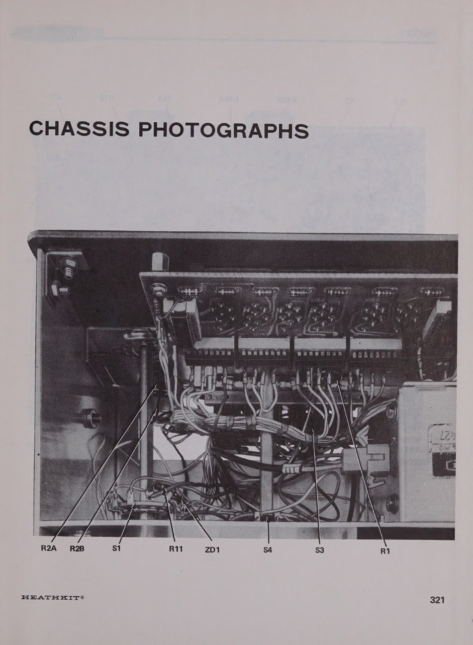
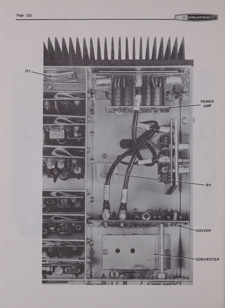
The chassis is divided into compartments by aluminium partitions, and each board slides into card guides and onto a row of chassis pins. The letters are Heath’s own, printed on labels under the chassis. The manual’s service section and every repair guide since are organised by them.
Table 1 — The board map
| Board | Function | Notes |
|---|---|---|
| A | Counter | prescaler, 1 MHz time base, five presettable decade counters and latches |
| B | Transmitter audio / regulator | microphone amplifier, VOX, sidetone, relay driver, 5 V and 11 V regulators |
| C | Transmitter IF / predriver | IF amplifier with ALC, balanced mixer, band-pass filters, predriver, CW keying |
| D | HFO / premixer | band crystal oscillators, VFO mixing, premix filters |
| E | Carrier generator / crystal filter | balanced modulator, three BFO crystals, SSB and CW filters, TX/RX switching |
| F | Receiver IF / audio | IF amplifier, AGC, product detector, audio filter and output |
| G | Receiver front end | preselectors, first and second mixers |
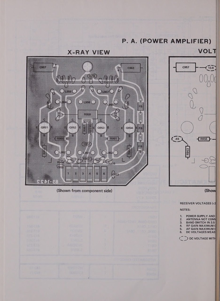
| H | Power amplifier | four RF power transistors on the rear heat sink |
| J | Driver | two driver transistors on the right side panel; LOW-power output path |
| K | ALC / output filter | low-pass filters, directional coupler, ALC timing |
| — | VFO oscillator and buffer boards | inside the sealed VFO box |
| — | VFO filter, display, converter | under the chassis, behind the panel, and in a shielded box |
| — | Noise blanker | optional SBA-104-1, plugs into its own socket |
Power arrives on an 11-pin plug. Pins 1, 2, 3 and 11 carry 13.8 volts to the final amplifier only. Pin 4 feeds everything else, which is why a rig wired with only pin 4 connected receives but cannot transmit (K5BCQ). Board B turns the 13.8-volt line into regulated 11 volts and 5 volts, with pass transistors mounted on the chassis. The 11-volt line runs the RF circuits and the diode switching. The 5-volt line runs the logic and feeds the only high voltage in the set: a 25 kHz converter in a shielded box that makes 180 volts for the display tubes.
2.2 The frequency scheme
Three oscillators set every frequency in the set, as in the tube SB rigs, but they are combined differently.
The BFO, on board E, is three separate crystal oscillators, one for each mode: 3396.4 kHz for upper sideband, 3393.6 kHz for lower sideband, and 3395.7 kHz for CW. Only one runs at a time, selected by the mode pushbuttons through transistor switches. The Operation manual describes the three as “identical except for the crystal frequency”.
The VFO is a field-effect transistor in a Hartley circuit. Part of coil L1201 and the main tuning capacitor set the frequency; the rest of the coil provides feedback; fixed temperature-compensating capacitors hold it steady. Diode D1201, switched by the voltage from the LSB button, adds or removes capacitors C1209 and C1211 so that “the output carrier frequency remains the same when you switch sidebands”. A zener regulates the oscillator’s drain supply. The oscillator drives a source-follower buffer and two fixed-tuned amplifiers, which are temperature-compensated by diodes. All of this is sealed in a box behind the tuning knob (SB-104 Operation manual, “VFO and Buffer Circuit Boards”).
The HFO on board D is a bank of crystal oscillators, one crystal per band position, selected by diodes. Each band’s HFO sits 8.895 MHz above the bottom of its band: 12.395 MHz for 80 metres, 22.895 MHz for 20 metres, and so on.
The new step comes next. On board D a diode balanced mixer combines the HFO with the VFO to make the premix signal, HFO minus VFO. The premix is filtered through diode-selected band-pass filters and amplified. On 80 metres it runs from 6.895 to 7.395 MHz as the VFO tunes. For any band, the operating frequency is the premix minus the 3.395 MHz IF. A Heath service bulletin on sweeping the filters gives the 20-metre case: at the 5.5 MHz VFO marker the premix is 17.395 MHz on board D and the signal is 14.0 MHz on board C (bulletin SB-104-74). Note that the operating frequency rises as the VFO frequency falls.
Premixing solves two problems at once. The transmitter needs only one mixer between the IF and the operating frequency, so there are fewer mixing products to filter. And there is now a single signal whose frequency, less the BFO, is exactly the operating frequency. The counter measures that signal.
2.3 The counter
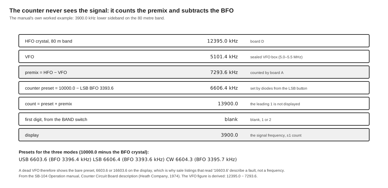
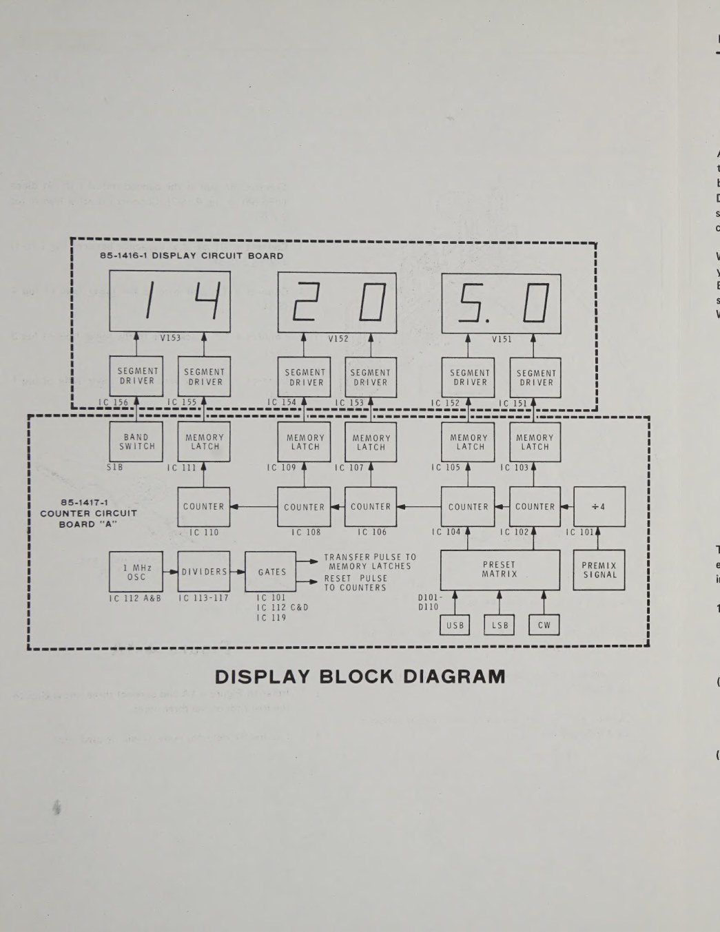
The counter board A does not measure the signal on the antenna. It measures the premix. Transistor Q101 amplifies the premix and a prescaler divides it by four. The manual says this reduces “ambiguity and flicker in the last (100 Hz) digit” and keeps the counters below their maximum frequency. A 1 MHz crystal oscillator is the time base, and a string of dividers produces the gate, transfer and reset pulses.
The subtraction is done by presetting. Before each count, the decade counters are loaded with a number equal to 10,000.0 kHz minus the BFO frequency. For lower sideband that is 6606.4. Counting the premix upward from there leaves the operating frequency in the counters, with a leading “1” that falls off the five-digit display. The manual’s worked example is 3900.0 kHz LSB: a premix of 7293.6 kHz plus the preset 6606.4 gives 13900.0, and the display reads 3900.0. The presets for USB and CW are 6603.6 and 6604.3. They are set by a diode matrix driven from the mode buttons, so the display stays correct when the mode changes and the BFO moves.
Latches hold each count while the next is taken, so the digits do not flicker. The display board’s segment drivers light six half-inch gas-discharge digits from the 180-volt converter. The first digit is not counted at all. It is driven from the band switch and reads blank, 1 or 2.
Because the counter includes the HFO and BFO as well as the VFO, Heath could claim “true digital frequency measurement circuitry that takes into account all three frequencies”. An SB-104 needs no crystal calibrator; its only reference is the 1 MHz time-base crystal, trimmed against WWV. The design also produces a diagnostic sign. If the VFO or its supply fails, no premix arrives and the display shows the bare preset: 6603.6, 16603.6 or 26603.6, depending on the band switch. K5BCQ notes that sale listings showing “16603.6 MHz” beside the words “works great” are describing exactly that fault (K5BCQ).
2.4 The transmitter
Audio, VOX and control (board B). A quad operational amplifier does four jobs. One section is the microphone and phone-patch preamplifier. It is disabled in CW and TUNE “to prevent microphone audio from being transmitted illegally”. A second section gives further gain after the MIC/CW LEVEL control and is muted on receive. A third drives the VOX detector. The fourth is the roughly 700 Hz sidetone oscillator. A transistor switch built from four transistors turns the VOX detector’s DC into a keying signal, and further transistors drive the chassis relay and handle push-to-talk.
Balanced modulator and filter (board E). Four hot-carrier diodes form the balanced modulator. The BFO signal, amplified by Q607, is mixed with the audio to produce a double-sideband signal with the carrier balanced out, set by the CARRIER NULL control and trimmer. The crystal filter then removes one sideband. Board E is also where the filter is shared. Transistor switches on each side of the filter route the modulator output through it on transmit and the receiver’s second-mixer output through it on receive. A second set of diode switches selects between the SSB filter and the optional 400 Hz CW filter. The SSB filter is the same 2.1 kHz part used in the tube SB rigs. The SBA-104-3 CW filter cannot be used in those older rigs, because it is designed around a different CW offset (Eckweiler, #30).
IF, mixer and predriver (board C). An integrated IF amplifier, IC301, amplifies the 3.395 MHz single-sideband signal. Its gain is controlled by the ALC voltage through transistor Q303. Q302 samples the ALC voltage for the panel meter. An emitter follower feeds a four-diode balanced mixer, where the IF and the premix combine to make the signal on the operating frequency. Diode-selected band-pass filters pick the wanted product. A two-transistor predriver amplifies it, and a second bank of band-pass filters follows. CW keying is done here, by switching the predriver’s emitter return on and off. A trap at 3.395 MHz, L321 with its capacitor, suppresses IF leakage on 80 metres. That trap became the subject of four service bulletins.
Driver (board J). Two driver transistors on the right side panel raise the signal to the level the power amplifier needs. Diodes D903 and D904 route the driver output either to the power amplifier (HI) or straight to the output filter and antenna (LO). In the one-watt position the power amplifier and the relay are bypassed entirely. The manual notes that “in the low power mode all transmit-receive switching is solid state”. A second pair of diodes rectifies part of the driver output to make the ALC voltage in low power.
Power amplifier (board H). The final is “two push-pull amplifiers operated in parallel”. Hybrid combiners split the drive between the two pairs and combine their outputs, and 100-ohm resistors across the input and output circuits keep the pairs balanced. Bias comes from a diode mounted in the heat sink, so “the bias voltage tracks with the heat sink temperature to prevent thermal runaway”. The amplifier is flat from 3 to 30 MHz. The manual states that “it is this characteristic that makes the ‘no-tune-up’ feature possible” (SB-104A Operation manual, Power Amplifier Circuit Board). The SB-104A assembly manual allows two types under the single Heath part number 417-831, the CTC CD-2664A and the 2N6456, with a different mounting pictorial for each. Earlier and later production used other makes. WB4KDI lists the Acrian S30-12A as the original device, and the Microsemi 2N6456, CTC CD-2664A and TRW PT5757 as the types fitted over the years. For the drivers he lists the TRW PT6619 and CTC CD-3342 (WB4KDI).
Output filter and ALC (board K). A broadband amplifier produces harmonics, and board K removes them with four low-pass filters: one each for 80, 40 and 20 metres, and one shared by 15 and 10 metres, since “the second harmonic of 15 meters falls well above the 10 meter band”. A rotary switch on the board, ganged to the band switch, selects them. The manual points out that “this is the only bandswitching in the Transceiver which is not solid-state, due to the power levels involved”. After the filters, a directional coupler samples forward and reflected power. The two samples are combined into the high-power ALC voltage, so a high SWR raises the ALC and cuts the drive. This is the SB-104’s protection against mismatched loads. It is real, but the repair literature is unanimous that it is not complete. Two transistors switch the ALC time constant between slow for SSB and fast for CW and TUNE.
2.5 The receiver
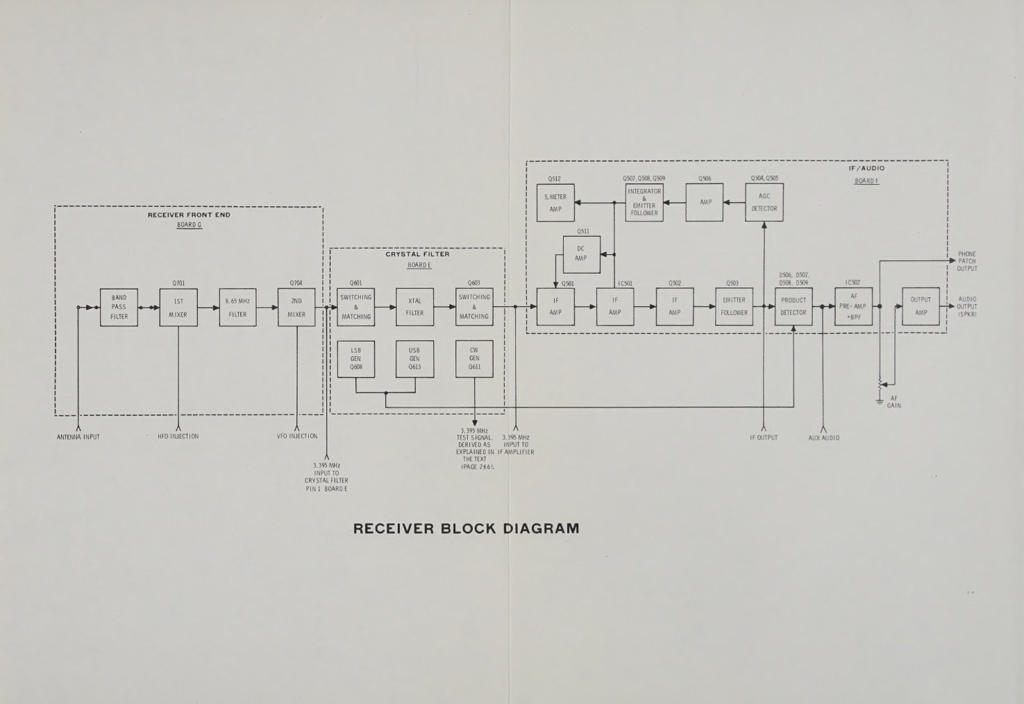
Front end (board G), SB-104 version. Diode-switched preselector filters, one per band, feed the antenna signal to the first mixer. The band switch applies +11 volts to forward-bias the diodes for the chosen filter and reverse-bias the rest. On transmit, +11 volts is applied so that every filter is reverse-biased and the receiver is isolated. A 5.0–5.5 MHz band-reject filter keeps VFO-frequency signals out. The first mixer combines the signal with the HFO to give a first IF between 8.395 and 8.895 MHz. This passes through a band-pass filter to the second mixer, where the VFO brings it down to 3.395 MHz. In the original board the mixers were dual-gate MOSFETs, type 40673, at Q701 and Q704.
Front end, SB-104A version. The redesigned board, supplied factory-assembled and aligned, keeps the same frequencies but changes the devices. The SB-104A manual describes an 8.395–8.895 MHz band-reject filter after the preselectors. Diodes D719 to D723 form a balanced first mixer. The first IF signal “is amplified by Q702 and filtered through an 8.395 to 8.895 MHz bandpass filter before it enters the second mixer”. Diodes D724 to D727 form the second balanced mixer (SB-104A Operation manual, Receiver Front End Circuit Board). Q702 is a 2N5109. K5BCQ measured an 8 dB improvement in signal-to-noise on 20 metres with the later board against the earlier one in otherwise identical conditions (K5BCQ).
Crystal filter (board E). On receive, transistor switches route the second mixer’s 3.395 MHz output through the same crystal filter the transmitter uses. The switches also match the filter’s impedance.
IF, AGC and detector (board F). A dual-gate MOSFET, an integrated IF amplifier and a further transistor provide the IF gain, and an emitter follower drives the detector and the AGC. The AGC is a peak detector feeding an integrator whose release time is switched between FAST and SLOW. A Darlington follower and a DC amplifier return the control voltage to the MOSFET’s second gate. The S-meter is driven from the same chain through a zener diode. The Restoration volume notes that the zener compresses the S-meter’s range. The product detector mixes the IF with the BFO. The recovered audio goes to a second quad op-amp, which forms a high-pass and a low-pass filter setting the 350–2450 Hz audio response, with the volume control between stages. A complementary output stage delivers 2.5 watts into 4 ohms.
Noise blanker. The optional SBA-104-1 plugs into its own socket. In the original wiring the signal always passes through it, even when it is switched off. That matters for strong-signal performance, and Heath’s own bulletin SB-104-69 of July 1978 rewired the switch to take it out of circuit.
2.6 Changing over
In HIGH power a chassis relay switches the antenna between the receiver and the power amplifier, driven by the relay transistor on board B. In LOW power everything is diode-switched. A rear-panel COM/SEP switch allows a separate receiving antenna. A separate set of relay contacts on the accessory socket switches an external linear amplifier. The launch spread made a point of the relay, the VOX and the TUNE button for “loading linear amplifiers”.
VOX works on voice for SSB. For CW it works on the keyed sidetone, which is fed to the VOX amplifier, so an operator can simply start sending. An ANTI-VOX control on the rear panel stops receiver audio from tripping the VOX.
2.7 The VFO filter board
A small board under the chassis sits between the VFO and board D. It is an attenuator pad and filter, and on the four 10-metre band positions a diode switch bypasses the pad to give the premix mixer more VFO drive. The manual adds that “the VFO filter prevents spurious premix products from entering the receiver injection circuits”. The board was among the first to be revised. Bulletin SB-104-30 (March 1976) disabled the bypass because “the high VFO injection which occurs when the VFO attenuator pad is bypassed on transmit” caused spurious signals on 10 metres. Bulletin SB-104-47 introduced a re-screened board. The SB-104A version, 85-1930-1, has three inductors where the early board had two. K5BCQ gives the early board’s number as 85-1633-2, but bulletin SB-104-47 gives 85-1516-1 and -2; the difference has not been resolved. K5BCQ’s measurements show the dilemma the board had to solve: with the VFO level too low the display becomes unstable, and with it too high the receiver produces birdies and the transmitter spurious signals.
2.8 What the design costs and what it buys
The SB-104 bought convenience at the cost of margin. A tube final with a pi network forgives a bad antenna, because the operator retunes it. A broadband transistor final into a 3:1 mismatch simply dissipates the difference, and the ALC must cut power fast enough to save it. A tube receiver with a tuned RF stage rejects signals far off frequency. A broadband front end with diode switching and diode mixers passes everything to the first mixer, so strong signals anywhere in the band become a problem. Every added oscillator, divider and converter is also a potential birdie. The SB-104A specification lists seven receive frequencies at which the rig hears itself. The Restoration volume shows how the service bulletins traced each of these problems.
The design is also easy to service, and that is still true. The same partitioned chassis and plug-in boards that let Heath offer 48-hour board exchanges let a modern owner swap a suspect board, put it on the extender, and measure it against the voltage charts printed beside every schematic in the manual.
Sources
- Heath Company. Heathkit Operation Manual, Single Sideband Transceiver Model SB-104 (copyright 1974): Theory of Operation; board Circuit Descriptions; block diagrams; Circuit Board Service Policy. Internet Archive (DLARC)
- Heath Company. Operation manual, SB-104A, 595-1994-06 (copyright 1977): Receiver Front End and Power Amplifier Circuit Descriptions; Specifications. RigPix
- Heath Company. Assembly manual, SB-104A, 595-1992-06 (copyright 1977), Transistor Installation, p. 1-129. PDF
- Ham Radio, November 1974, Heathkit centre spread. PDF
- Heath Company, SB-104 service bulletins (1975–1989), W7LPF transcription. Nostalgic Kits Central
- K5BCQ. “Heathkit SB-104, HW-104, SB-104A Transceiver Repair.” Link
- WB4KDI Engineering Notebook. “Help! I Just Got a SB/HW-104.” Link · HW-104 index
- Eckweiler, Bob (AF6C). “Heathkit of the Month #30: The Amateur Radio SB-Line Overview.” PDF
Comments (0)