ET-3100 Analog Trainer · Volume 5
Restoration and Common Faults
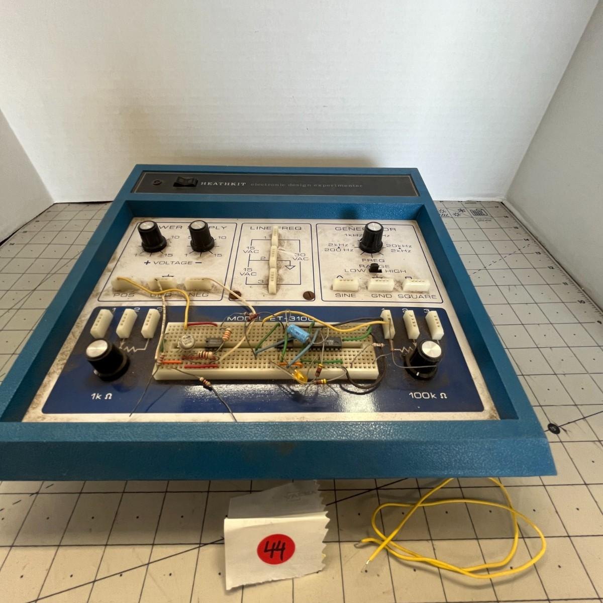
ET-3100s survive in large numbers. Schools bought them by the classroom and home students kept them, and they turn up at estate sales and on auction sites still carrying the last circuit someone left on the breadboard. The circuit is simple, the parts are mostly common types, and nothing inside runs hot. Restoration is therefore mostly a matter of mains safety, capacitors, contacts and, on the original version, one small lamp. This volume works through them in that order.
5.1 Safety first
The ET-3100 is a low-voltage instrument on its outputs, but it runs from the mains. The original version was designed before Heath’s later safety revisions, and a unit of fifty years’ age needs to be treated accordingly.
- Know which version is on the bench. The original ET-3100 has a two-wire line cord with no earth, knotted inside the case for strain relief, a neon pilot lamp wired across the transformer primary, and a 1/8 A fuse held in clips inside the mains box. The ET-3100A and ET-3100B have a three-wire cord, a fuse holder in the side of the cabinet and an LED pilot (HotM #129). The pilot is the quickest way to tell: an orange neon glow means an original; a red LED means an A or B.
- The mains is exposed when the box cover is off. All the primary wiring sits in the moulded box in the cabinet bottom, under a screwed insulator plate. The B manual’s test section warns: “do not touch the area marked ‘High Voltage Area.’ 120 VAC is present at these locations when the line cord is plugged into an AC outlet” (ET-3100B manual, p. 28). The power-switch lugs, on the board, are also at mains potential, protected by heat-shrink on the B and by an insulator added in the A. Never operate the trainer on the bench with the board lifted out unless the insulator plate is in place and the switch lugs are covered.
- Check the line cord and strain relief before plugging in. A knotted two-wire cord that has been flexed for decades can crack at the knot. Replacing it with a three-wire cord, with the earth taken to the transformer frame and the board’s common foil as Heath did on the A and B, is the single most useful safety upgrade for an original unit, and it is a modification Heath itself made.
- Fuse correctly. The original takes a 1/8 A slow-blow fuse and the B a 1/4 A slow-blow. A larger fuse protects nothing in a 7 W instrument.
- Bring it up slowly. For a unit of unknown history, a first power-up through a variac or a dim-bulb tester (a 25–40 W incandescent lamp in series with the mains) will show a shorted rectifier or filter capacitor as a glowing bulb rather than a blown fuse or a cooked transformer.
- Never “test” it by touching the LINE FREQ blocks. They carry only 15 and 30 V AC and are isolated from the mains by the transformer, but that isolation depends on a transformer whose insulation is now half a century old. Measure them with a meter.
5.2 What actually fails
5.2.1 Filter capacitors
The two main reservoir capacitors (C101 and C111, 1000 µF; the original schematic says 1200 µF, 30 V) and the smaller 10 µF electrolytics across the zener references are the oldest parts in any ET-3100 and the likeliest to have dried out. The symptoms are hum and ripple on the POS and NEG outputs at higher currents, a supply that sags or oscillates under load, and, if the zener reference capacitors have failed, a generator whose sine wave is modulated at 120 Hz. W0MPM, restoring one for his own bench, found the supplies “poorly filtered and regulated” and fitted larger capacitors, with extra bypassing, to improve them (W0MPM).
Replacement is straightforward. Modern 1000–2200 µF electrolytics at 35 V fit easily. The raw supply is about 21 V on the original and 26 V on the B, so a 35 V rating gives margin on both, and a larger value costs nothing but a little more inrush current on a 200 mA winding. On the B the reservoirs are mounted on the foil side on foam tape, and the foam should be renewed or the new capacitors secured with a dab of silicone. Observe polarity; the negative supply’s reservoir has its positive lead to ground.
5.2.2 The oscillator lamp (ET-3100 and ET-3100A)
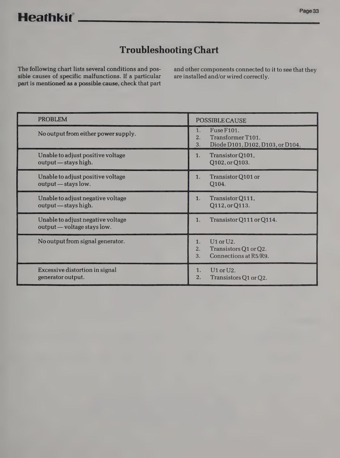
The small incandescent lamp L1 (Heath 412-83) is the one part in the original generator that has no direct modern equivalent on a catalogue shelf. It fails in two ways. An open filament stops the oscillator dead, because without the lamp the op-amp has no negative feedback path to ground. A tired filament, or a replacement with the wrong cold resistance, leaves the oscillator unable to settle: it clips, or it “bounces” (the amplitude swells and shrinks for several seconds after each change of frequency), or it quits on one end of a range. The manual’s troubleshooting chart lists “Control R4 misadjusted” and “IC1” as the causes of both a dead and a distorted generator; the lamp belongs on that list too (ET-3100 manual, p. 27).
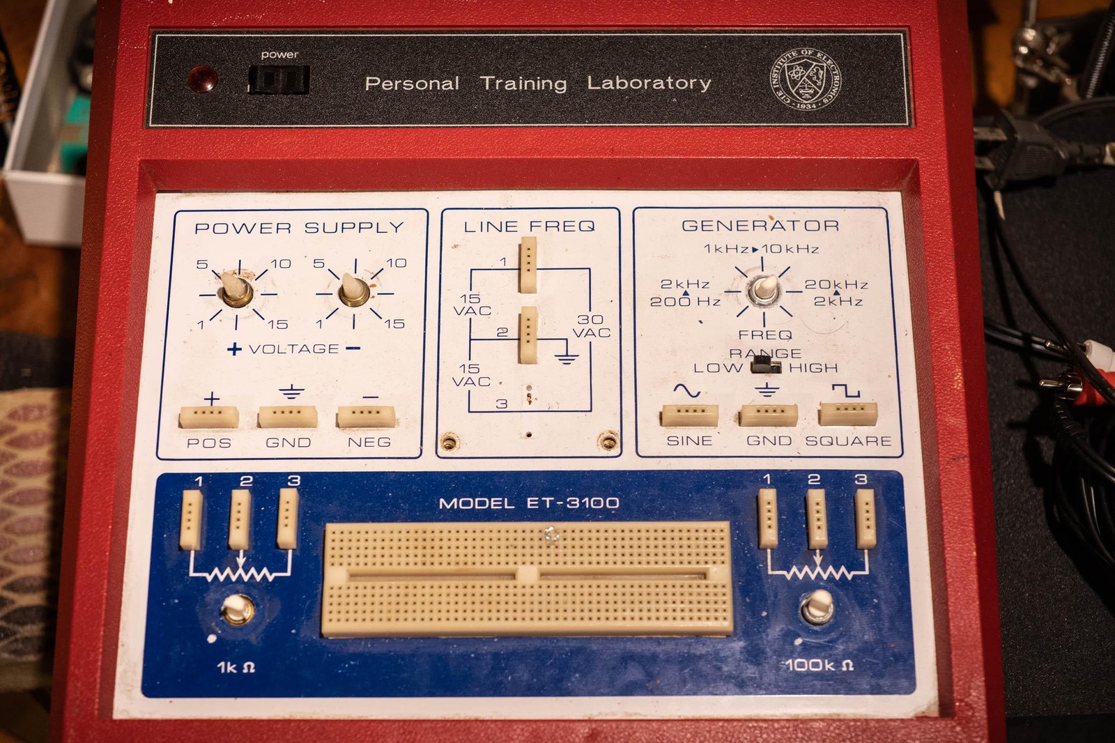
Heath’s documents do not give the lamp’s electrical rating, and none has been confirmed from other sources for this dive. The problem is familiar enough that owners ask about it online (one such request, with a photograph of a red OEM unit, is shown below). The practical course is to fit a small, low-current incandescent lamp of the kind used for Wien-bridge stabilisation, as close as can be judged to the original’s size and cold resistance, and then re-set R4 by the manual’s procedure. With the lamp dimly lit, turn R4 until the filament just goes dark, then back until it just glows, or set it on an oscilloscope for the largest undistorted sine wave (ET-3100 manual, p. 21). The procedure matters more than the exact lamp, because R4 has enough range to accommodate a moderate difference in lamp resistance. More radical fixes (a JFET or thermistor gain control, or replacing the generator with a modern function-generator IC) work, but they are modifications rather than restoration and should be recorded as such.
The ET-3100B has no lamp. Its zener-limited LM301 oscillator has no settling time and no adjustment, and it very rarely fails; when it does, the chart points to U1 and U2 and to the zeners ZD1 and ZD2.
5.2.3 The neon pilot (ET-3100)
The NE-2-type neon lamp across the primary (412-15 with a 27 kΩ resistor) darkens with age and eventually flickers or fails to strike. A new neon lamp of the same type is the authentic repair. Heath’s own replacement was an LED: on the ET-3100A the pilot became a red LED fed from the +15 V zener through 1 kΩ, with the zener’s feed resistor reduced from 220 Ω to 150 Ω (1 W) to supply the extra current (HotM #129). That conversion also removes one mains-potential component from the board.
5.2.4 Controls, switches and contacts
- Potentiometers. The five panel controls are plain carbon types and become scratchy. On the supplies this shows as a voltage that jumps as the knob turns. On the generator the dual FREQ control (100 kΩ dual, Heath 12-146, on the original; 200 kΩ/5 kΩ dual, 12-184, on the B) matters most, because a dirty track on one half unbalances the bridge and the oscillator drops out at part of the rotation. Contact cleaner and exercise usually cure it. A replacement dual control of the right values and taper is the one part most likely to need hunting for.
- The RANGE slide switch (DPDT, Heath 60-78) oxidises; a range that works only when the switch is pressed is the symptom. It is soldered to the foil by its tabs and can be cleaned in place.
- The rocker power switch (60-607) is a common type, but its lugs are at mains potential and any replacement must be insulated as the original was.
5.2.5 Breadboard and connector blocks
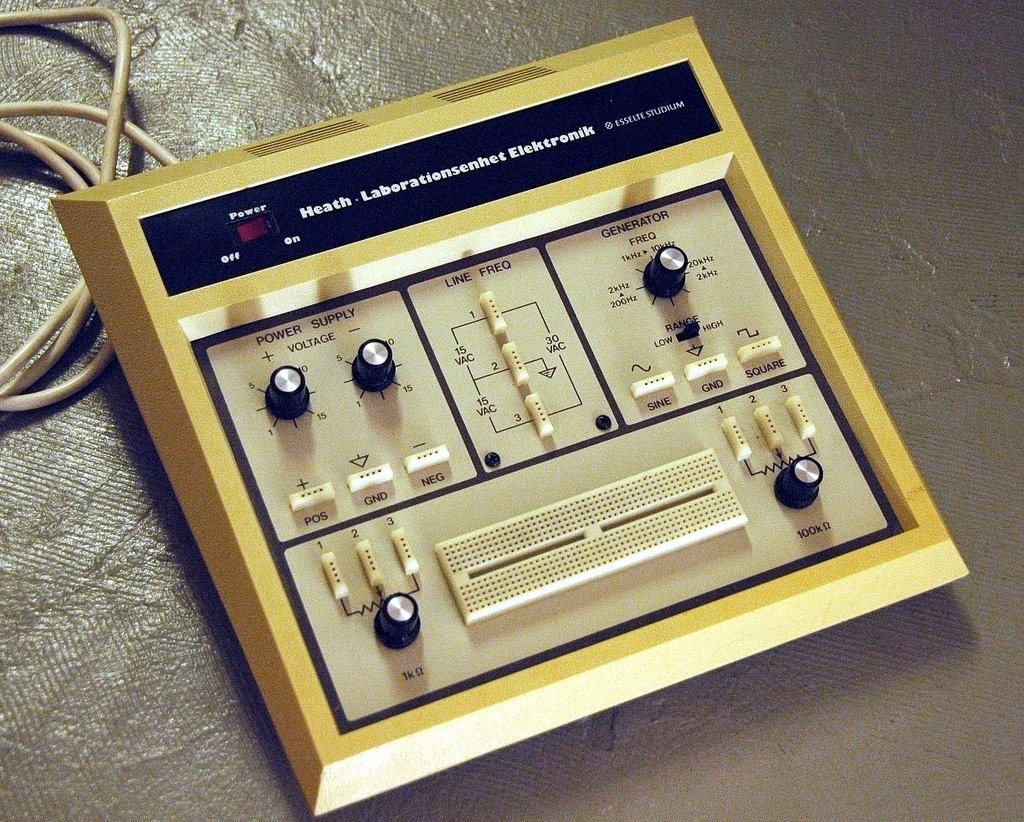
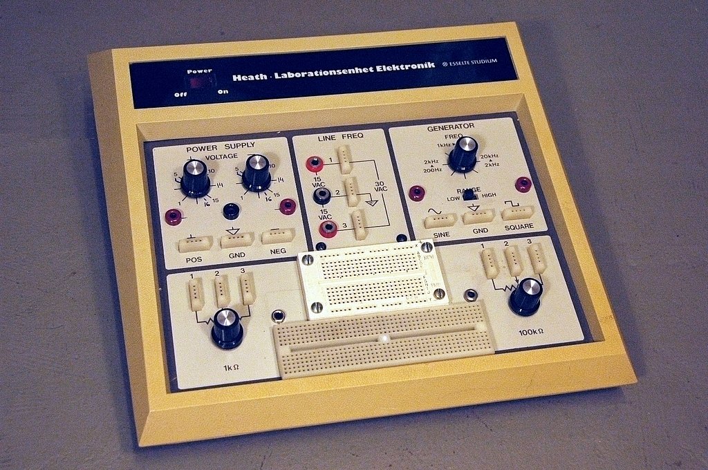
The breadboarding socket (432-875) and the fifteen four-hole connector blocks (432-874) take the most wear. Decades of oversized component leads and stranded wire spread their spring contacts until a thin lead makes intermittent contact. The contact strips in the socket were pressed in by the builder and can be pushed out from below for inspection. The standard modern cure is to replace the socket with a new solderless breadboard of the same 0.1-inch pitch, fitted into the same opening or mounted over it. A larger one can be used if the owner does not mind losing originality; the Swedish school unit shown below had its breadboard extended in exactly this way (heathkit.nu). The connector blocks have no direct modern equivalent, and worn ones are best retensioned with a fine pick rather than replaced.
5.2.6 Semiconductors
The semiconductors are rarely the problem, and they are all either still made or have easy substitutes.
Table 1 — Semiconductors
| Part | Where | Notes |
|---|---|---|
| 741 (N5741V, MC1741CP1, LM741CN) | IC1, ET-3100/A generator | Still made; socketed |
| LM301 | U1, U2, ET-3100B generator | LM301A still made; socketed |
| MJE181 / MJE171 | Q102 / Q106 pass transistors, ET-3100/A | Common TO-126 complementary pair |
| MJE5979 / MJE5976 | Q102 / Q112, ET-3100B | Obscure numbers; any TO-126 or TO-220 power pair of similar rating fits on the heat sinks, with the pinout checked |
| MPSA20 (417-801) | regulators, squarer | Obsolete; a general-purpose NPN of the same pinout (E-B-C as drawn in the manual’s identification chart) substitutes |
| 2N4121 (417-235) | negative regulator, Q2 | General-purpose PNP; same caution on pinout |
| 1N4149, 1N4002, 15 V zeners (1N4744A) | throughout | Standard |
Always check a substitute’s lead order against the manual’s semiconductor identification chart. TO-92 pinouts vary between makers and the board is marked E, B, C.
5.3 Working through a fault
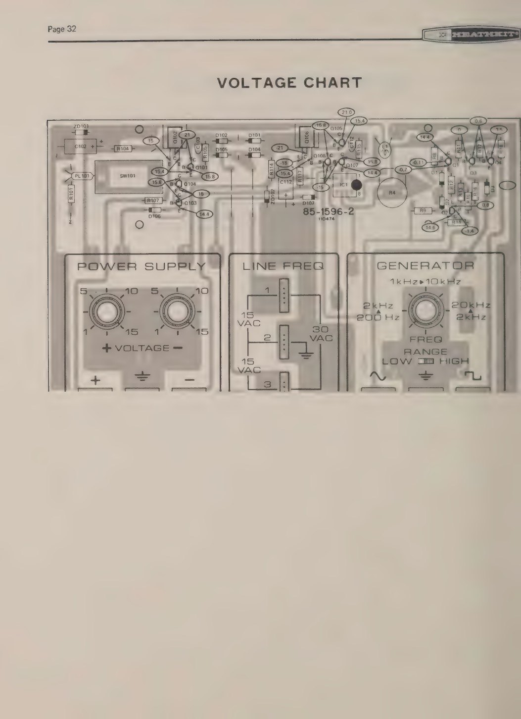
Both manuals give DC voltages at every transistor terminal, measured with both supplies set to 15 V, and the original adds a full-page voltage chart drawn over the board layout. With a high-impedance meter and the charts, faults locate quickly:
- No output from either supply: fuse, transformer, the bridge rectifiers or a shorted reservoir capacitor. Check for about ±21 V (±26 V on the B) across C101 and C111.
- One supply stuck high: the error amplifier (Q103 or Q113) or its reference diode is open, or the Darlington pass transistor has shorted collector to emitter. The manual’s chart names “Q101, Q102, or Q103.”
- One supply stuck low, or current-limiting at no load: the current-limit transistor (Q104) is leaky, the sense resistor has gone high, or there is a short on the output wiring or breadboard.
- Generator dead, supplies fine: on the original, the lamp L1, the 741 or R4; on the B, U1 or U2. Check the ±15 V zener references first, because the generator runs from them.
- Sine present but no square: the squarer transistors.
5.4 Modifications, period and modern
Heath’s own revisions (the ET-3100A’s three-wire cord, fuse holder and LED, and the ET-3100B’s heavier supplies and lamp-free generator) are the best guide to what the original needed, and the safety changes are worth copying onto any original unit kept in use.
Owners have added more:
- Terminals for instruments. The Swedish Esselte unit documented at heathkit.nu had 4 mm test terminals added beside the supply and generator blocks, so that a VTVM or oscilloscope could be connected without pushing wire into the blocks (heathkit.nu).
- A larger breadboard. The same unit had its breadboard extended. Eckweiler also judged the breadboard the trainer’s main weakness for use after the courses.
- A panel voltmeter. W0MPM fitted an inexpensive digital panel voltmeter to the positive output, powered from its own isolated supply through an isolation resistor to keep its noise out of the trainer, along with larger filter capacitors and an external fuse holder (W0MPM). Heath’s own successor, the ET-3600, added a digital voltmeter through its accessory Backpack, which suggests Heath saw the same need.
Any modification that cuts the board’s printed panel is irreversible, and the silkscreened legends are the board. Additions are best made on the cabinet sides or on a separate plate.
5.5 Cosmetics
The cabinet is moulded plastic (blue on the originals, beige on later Heathkit/Zenith units, other colours on OEM versions) and cleans with mild detergent and water. The panel is the silkscreen on the circuit board itself, and it deserves more care. Solvents that are safe on a painted metal panel can soften or lift board legends, so a test on an inconspicuous corner is prudent before anything stronger than soapy water is used. The B manual has the builder clean the cabinet bottom with alcohol before applying labels, which says nothing about the board face. Knobs pull off; the B’s two-part knobs have a pressed-in bushing and are best left assembled.
5.6 Is it worth restoring?
As an instrument, an ET-3100 is a modest thing: two 100 mA supplies and an audio oscillator that a modern bench outperforms. Its value lies elsewhere. It is the laboratory that went with a course, and a working one with its binder and records is a complete artefact of how electronics was taught at home in the 1970s. The work is cheap: capacitors, a lamp, cleaning, and on an original a safer line cord. The unit also remains useful as a breadboarding station for op-amp and audio work, which is the use Heath promised for it after the course was finished.
Sources
- Heath Company, ET-3100 assembly manual, 595-1734-06 (parts list pp. 3–7; test p. 21; troubleshooting p. 27; voltage chart p. 32): https://archive.org/details/manualsplus_11837
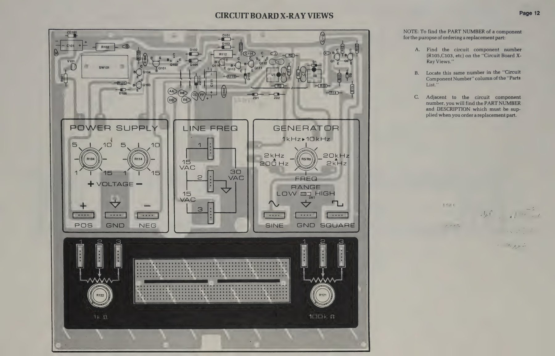
- Heath Company, ET-3100B assembly manual, 595-2860-03 (test p. 28; troubleshooting chart p. 33; semiconductor chart p. 36; X-ray view): https://archive.org/details/heathkitmanualfo00unse_0
- Bob Eckweiler, AF6C, Heathkit of the Month #129, rev. 1, 2026: https://www.w6ze.org/Heathkit/Heathkit_129_ET3100B.pdf
- heathkit.nu, ET-3100 page (Esselte OEM unit and modifications): http://heathkit.nu/heathkit_nu_ET-3100.html
- W0MPM, “Heathkit ET-3100 Experimenter and Breadboard”: https://qsl.net/w0mpm/HeathkitET3100.html
Comments (0)