ET-3100 Analog Trainer · Volume 4
The Courses and the Bench
A test instrument’s manual usually ends with calibration. The ET-3100’s ends with two sample circuits and a note that the experimenter “not only supplies positive (+) and negative (−) DC voltages, but also 15 and 30 volts AC, and both sine and square wave signals from 200 Hz to 20 kHz.” There was nothing to calibrate, because the trainer’s real instructions were in the course binders. This volume covers the controls and their practical use, the Individual Learning Program courses the trainer was designed for, what a student actually did with the two together, and the classroom versions that took the same materials into schools.
4.1 The controls

The panel has three labelled sections and a breadboard, and every output appears on a connector block.
Table 1 — The controls
| Section | Controls | Connector blocks | Notes |
|---|---|---|---|
| POWER SUPPLY | + VOLTAGE and − VOLTAGE knobs, each marked 1–5–10–15 | POS, GND, NEG | Two independent supplies sharing GND. The knob scales are only a guide; a meter is needed for an accurate setting |
| LINE FREQ | none | 1, 2, 3 | 15 V from 1–2 and 2–3, 30 V from 1–3; block 2 is ground. Always live when the trainer is on |
| GENERATOR | FREQ knob, RANGE slide switch LOW/HIGH | SINE, GND, SQUARE | Dial marked 200 Hz–2 kHz (LOW) and 2–20 kHz (HIGH), with 1 kHz / 10 kHz at the top |
| Experimental controls | 1 kΩ and 100 kΩ knobs | 1, 2, 3 for each | Blocks 1 and 3 are the ends of the track, 2 the wiper; not connected to anything else |
| Breadboard | — | 96 strips of five holes | No built-in rails; wire from POS, GND and NEG to the strips used as rails |
Several practical points follow from the circuit (see the circuit volume) and appear nowhere in the manuals as warnings.
- The square wave is unipolar. It swings from about 0.1 V to +15 V, not ±7.5 V, because it is the collector of a saturated transistor pulled up to the +15 V reference. A student wanting a symmetrical square wave had to couple it through a capacitor. Its duty cycle is about 30%, not 50%.
- The sine output is 1 V rms from 600 Ω. Loading it with a few hundred ohms halves it. The 100 kΩ control makes a convenient attenuator.
- The generator ignores the VOLTAGE knobs. It runs from the fixed ±15 V zener references, so it works with both supplies turned down.
- The supplies do not go to zero. Their minimum is about 1.2 V. Experiments needing a fraction of a volt used a potentiometer as a divider.
- The AC and DC share a budget on the original. On the ET-3100 and ET-3100A, the manual limits the total drawn from all supplies to 200 mA. The ET-3100B gave the AC outputs their own winding.
- Wires. The connector blocks take solid wire up to #20 (0.032 inch); Heath recommended #22 or #24 and supplied it in the kit. Stranded wire and fat component leads spread the contacts.
- ICs. “The breadboarding socket is designed to accommodate integrated circuits and the IC puller supplied in your kit. This IC puller fits down into the center channel of the breadboarding socket to gently and easily lift the IC out” (ET-3100B manual, p. 30).
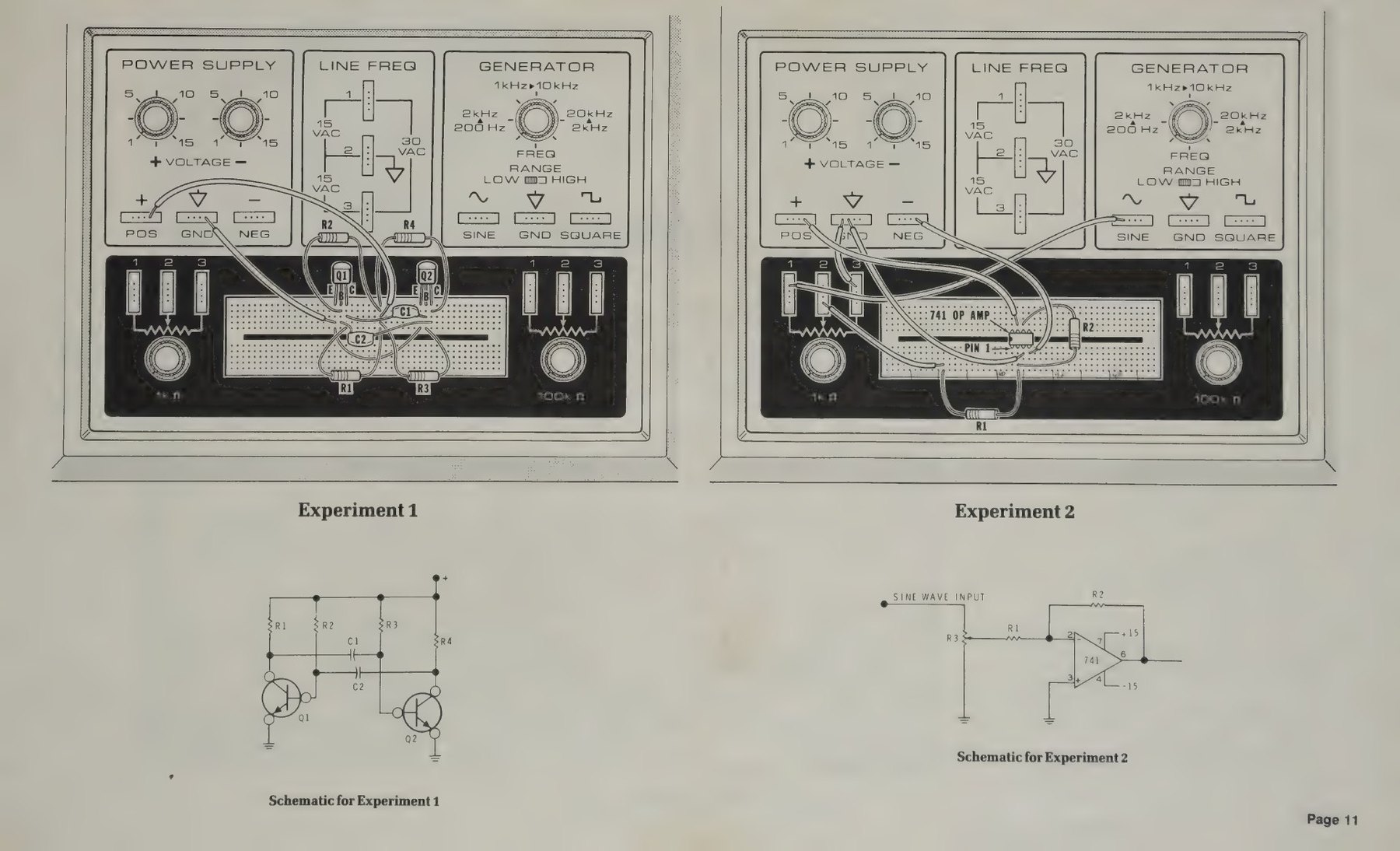
The manual’s two examples show how the trainer was meant to be used. Experiment #1 is a two-transistor astable multivibrator powered from POS and GND. Experiment #2 is a 741 inverting amplifier: the SINE output goes into the 1 kΩ control used as a level control, then into the op-amp through R1, with R2 as feedback and the op-amp powered from both supplies. Between them they use every section of the panel except LINE FREQ.
4.2 The Individual Learning Program
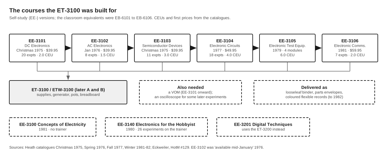
Heath marketed its home-study courses as the Heathkit Continuing Education Series of Individual Learning Programs (the words on the binder spines are “Heathkit Continuing Education” and “Individual Learning Program”). The first four analog courses formed a sequence, each the prerequisite for the next:
Table 2 — Heath marketed its home-study courses as the Heathkit Continuing Education Series of Individual Learning Programs (the words on the binder spines are "Heathkit Continuing Education" and "Individual Learning Program"). The first four analog courses formed a sequence, each the prerequisite for the next
| Course | Title | Units | Experiments | Parts | CEU | Records |
|---|---|---|---|---|---|---|
| EE-3101 | DC Electronics | 8 | 20 | 56 | 2.0 | 7 (449-115) |
| EE-3102 | AC Electronics | 6 | 8 | 34 (1976) / 16 (1978) | 1.5 | (449-116) |
| EE-3103 | Semiconductor Devices | 10 | 11 or 27 (see below) | 27 or 11 | 3.0 | (449-117) |
| EE-3104 | Electronic Circuits | 7 | 18 | over 110 | 4.0 | (449-118) |
Unit lists, experiment and parts counts and CEU values are from the Spring 1976, Fall 1977 and Fall 1978 catalogues; record part numbers are from the “Open this package first” sheet bound into a 1983 EE-3101 binder (EE-3101, Internet Archive). The Semiconductor Devices counts conflict: Spring 1976 says “11 parts for 27 experiments”, Fall 1977 says “27 parts for 11 different experiments”. The later wording is the more plausible, since 11 components could not furnish 27 semiconductor experiments.
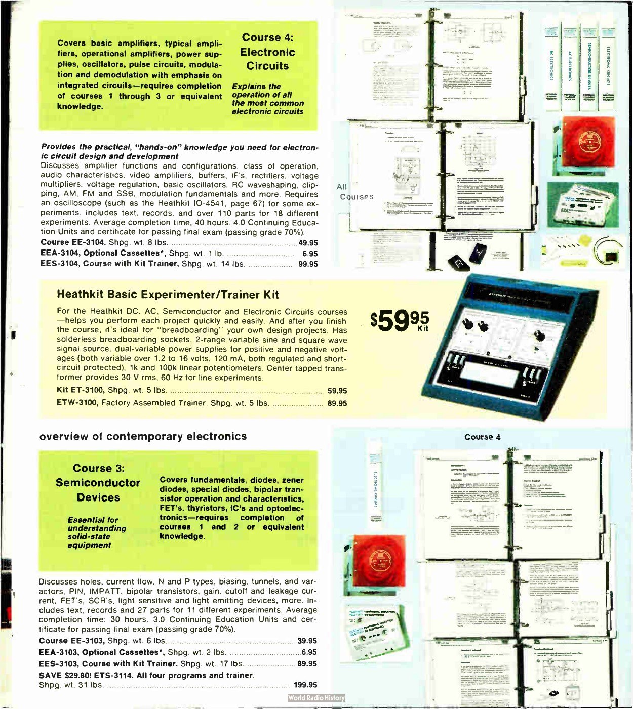
The contents followed a textbook progression. DC Electronics covered electron theory, voltage, resistance, Ohm’s law, magnetism, electrical measurements, network theorems, and inductance and capacitance. AC Electronics covered AC fundamentals, AC measurements, capacitive and inductive circuits, transformers and tuned circuits. Semiconductor Devices ran from semiconductor fundamentals through diodes, zeners, special diodes, bipolar transistors, FETs, thyristors, ICs and optoelectronics. Electronic Circuits covered basic and typical amplifiers, operational amplifiers, power supplies, oscillators, pulse circuits and modulation (Christmas 1975; Fall 1977). Two further courses completed the “Basic Electronics Series”: EE-3105 Electronic Test Equipment, in four separately bound modules on meters, oscilloscopes, frequency measurement and generation, and special instruments (introduced in 1979), and EE-3106 Electronic Communications (1981), with seven experiments that built an AM transmitter, a balanced modulator, an FM transmitter and receiver, a pulse modulator, a time-division multiplexer and a data modem, all on the ET-3100 (Winter 1981–82, p. 74). EE-3140 Electronics for the Hobbyist (1980) condensed the series into two binders with 26 experiments on the same trainer (HotM #129).
4.2.1 How a course was studied
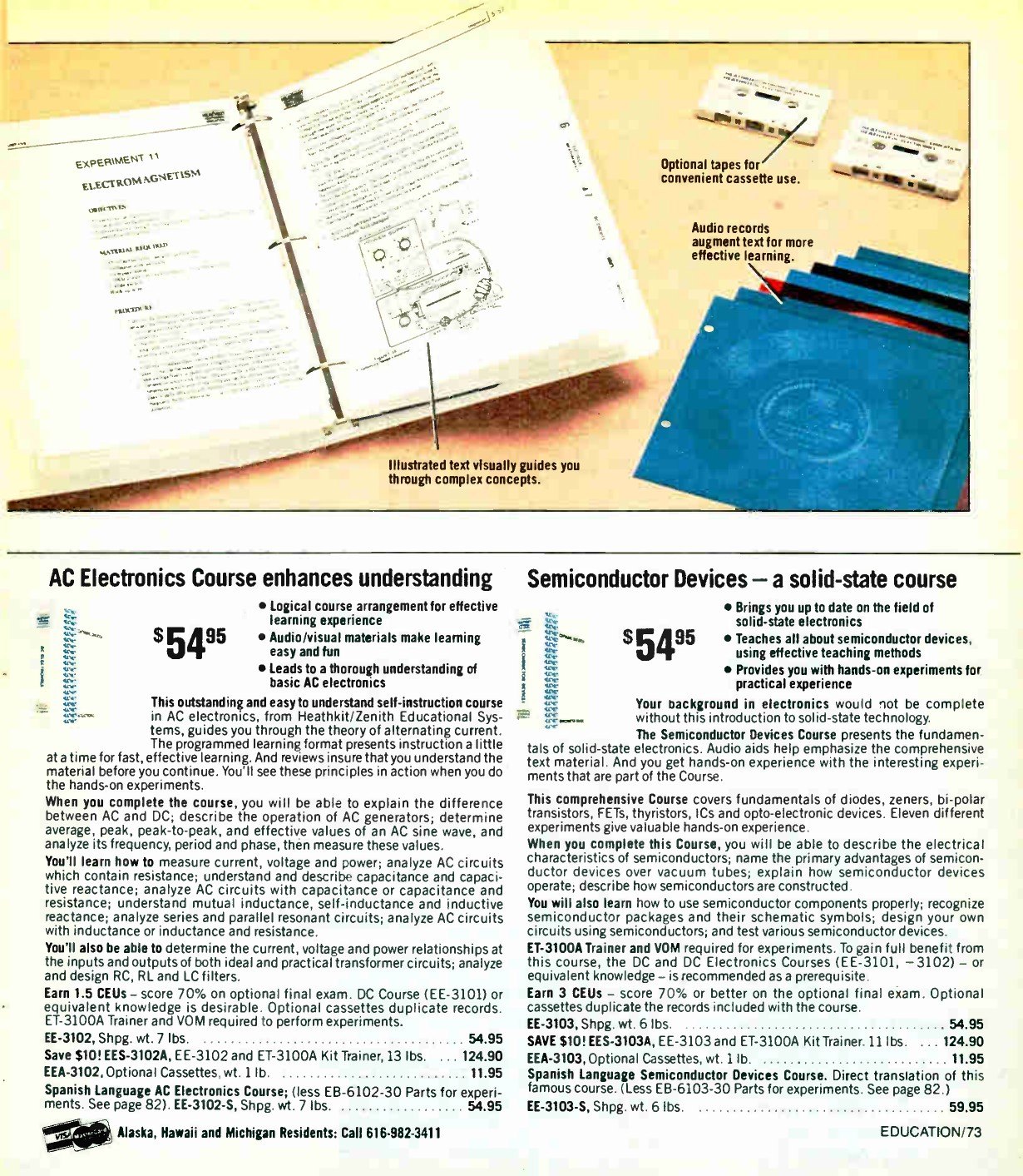
Each binder arrived as loose printed sheets, tab dividers, bags of parts and a packet of records, and the student’s first job was to assemble it. The instruction sheet in the 1983 EE-3101 is headed “OPEN THIS PACKAGE FIRST!” and ends with: “Begin your program. Start by playing Audio Record 1 then Audio Record 2. Follow the instructions given on these records” (EE-3101, 595-1781-04). The records were punched to clip into the binder’s rings. From 1977 Heath offered the same audio on cassette at extra cost, and in late 1982, with the “A” editions, it dropped the records in favour of an optional audio-visual accessory: two cassettes and an illustration booklet (HotM #129).
Every unit followed the same pattern: objectives, a “Unit Activity Guide” listing the order of reading, listening and experiments, programmed text in short numbered frames, each ending in a blank whose answer is printed at the start of the next, one or more experiments, a summary and a self-graded unit examination. The final examination came in its own Final Examination Kit envelope; a score of 70% earned a certificate and the course’s Continuing Education Units. By 1982 the American Council on Education recommended that colleges give credit for some of the courses, and Heath sold a separate proctored “College Credit Program Exam” for each, ordered by changing the course prefix to ECC (Christmas 1982, p. 31).
4.2.2 What the experiments did with the trainer
The first experiment of DC Electronics shows the relationship. Its stated objectives are “To gain practice measuring voltage. To familiarize you with the operation and capabilities of the Electronic Design Experimenter and your meter. To determine how the two power supplies on the Electronic Design Experimenter are connected.” The introduction explains the POWER SUPPLY panel with a drawing of it, and the procedure begins: “Plug in the Experimenter and turn the ON-OFF switch to the ON position. Turn both voltage control knobs fully counterclockwise” (EE-3101, Unit 2, Experiment 1). Every experiment opens with a “MATERIAL REQUIRED” list, and almost every one begins “1 ET-3100 Electronic Design Experimenter”, followed by a meter and the parts from the course bag.
The DC course’s twenty experiments include voltage rises and drops, shorts and opens, the resistor colour code, the ohmmeter, a light-dependent resistor, current measurement, power, magnetic and electromagnetic devices (with a compass from the parts bag), the sensitivity of the student’s own voltmeter, bridge circuits, network theorems, maximum power transfer, and series and parallel capacitors. AC Electronics adds the generator and an oscilloscope: AC measurements, RC circuits, capacitor applications, series and parallel resonance, LC filters and transformer characteristics. Electronic Circuits covers amplifiers, active filters, voltage regulation, ramp generators and amplitude modulation, and its Unit 4 ends by analysing the ET-3100’s own power supply: “As our final example, let’s consider the power supply in the ET-3100 electronic design Trainer” (EE-3104-B). A student who reached that page could open the trainer and find the circuit being described.
Heath’s catalogue copy was candid about what else was needed: a VOM for everything from EE-3101 onward (the IM-17, later IM-5284 and IM-2260), a record player (early ads offered a Heath phonograph for anyone without one), an oscilloscope such as the IO-4105 for some AC and circuits experiments, and for EE-3105 the test instruments each module was about. Eckweiler observes that the Test Equipment course “surely contributed to the sale of a lot of Heathkit test equipment” (HotM #129).
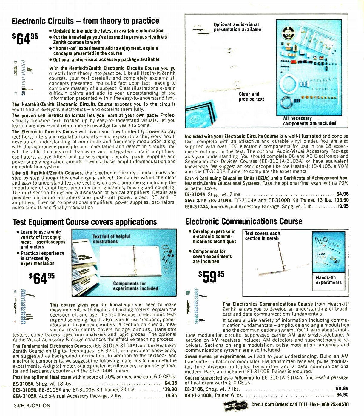
4.3 From the kitchen table to the classroom
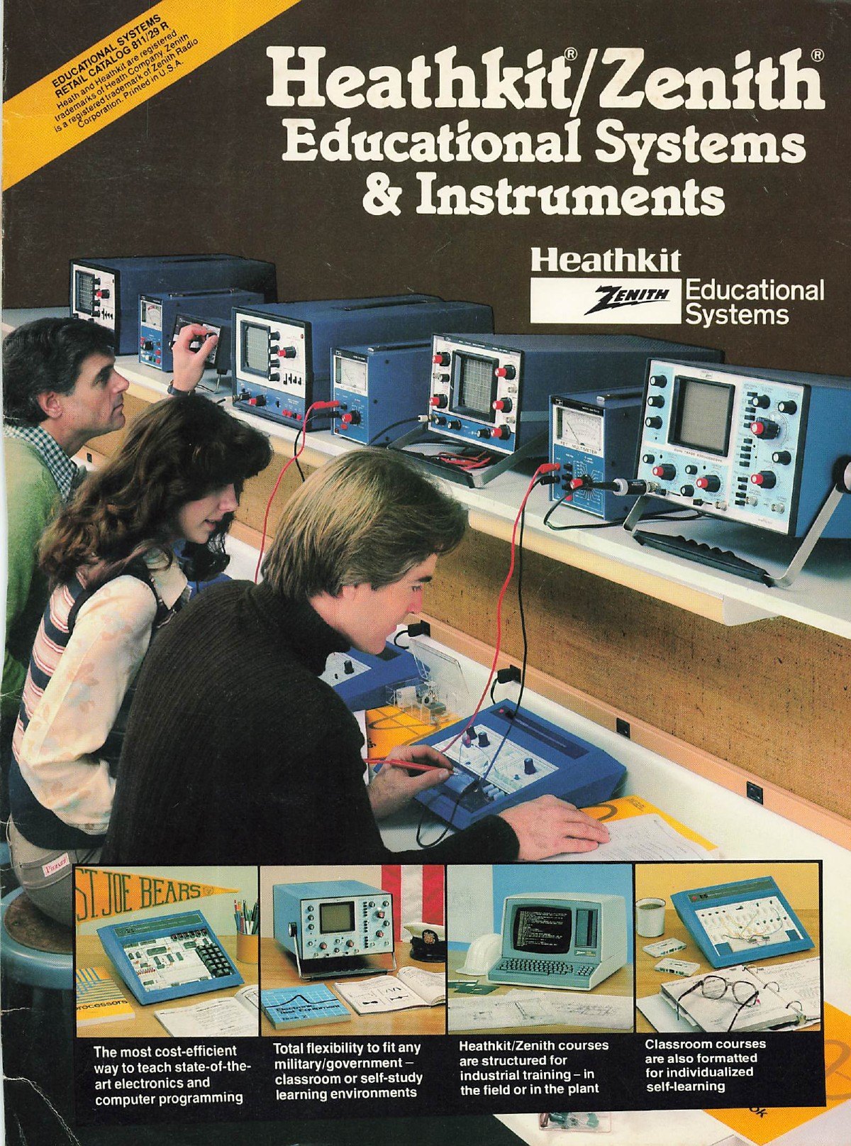
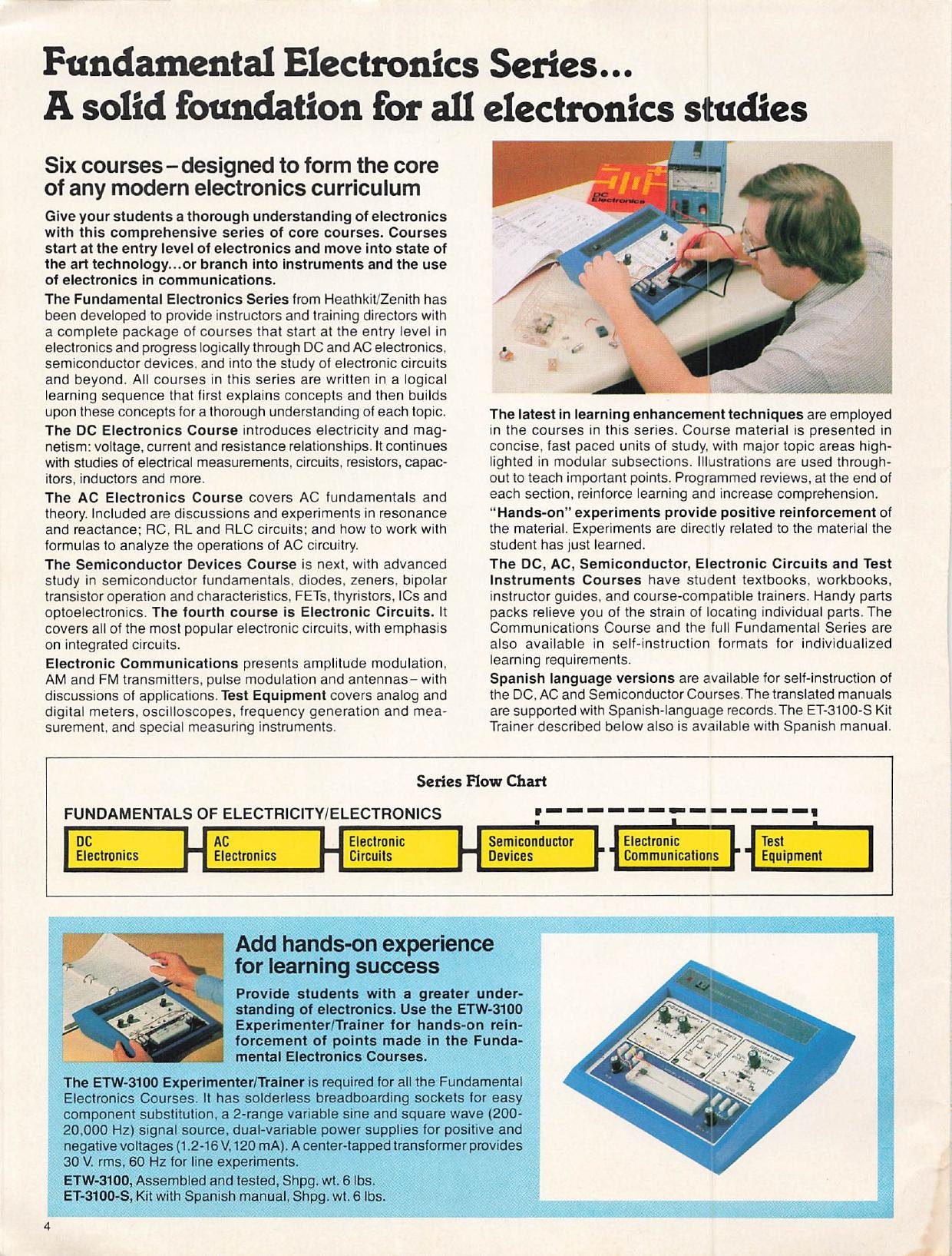
Heath’s educational business began with schools as well as home students; Brueschke and Mack date Heathkit Educational Systems to 1974 (history dive, vol. 4). By the early 1980s the same courses were being sold to schools, industry and the military through a separate catalogue, Heathkit/Zenith Educational Systems & Instruments. Its “Fundamental Electronics Series” lists six courses (DC, AC, Electronic Circuits, Semiconductor Devices, Electronic Communications and Test Equipment) each in two formats. The classroom version had a student textbook (EB-6101 for DC, EB-6102 for AC, EB-6103 for semiconductors), a student workbook (-40), an instructor’s guide (-50) and a parts package (-30). The self-instruction version was the familiar EE-310x binder. For both, “The ETW-3100 Experimenter/Trainer is required for all the Fundamental Electronics Courses,” and Spanish-language editions of the DC, AC and Semiconductor courses were supported by an ET-3100-S kit with a Spanish manual (Heathkit/Zenith Educational Systems catalogue 811-29R, pp. 4–7).
World Radio History files that catalogue under 1975. Its contents place it later: the Heathkit/Zenith name dates from after Zenith’s purchase of Heath in October 1979, and its cover shows an all-in-one Zenith computer on the lab bench. It is best read as a catalogue of about 1980–81.
The trainer outlived its own name in the course texts. The fifth edition of DC Electronics (EE-3101-C, 1998) tells students that “the experiments will work on a wide variety of Heathkit Trainers. These include the ET-3100 series, ET-3600s, and the ET-1000” (EE-3101-C). The fourth edition of AC Electronics (1999) asks for “a Heathkit Analog Trainer, such as the ET-3600” (EE-3102-C). Both carry copyright dates going back to 1975, and the third edition of Electronic Circuits still uses the ET-3100’s power supply as its worked example. By 2001 the classroom Semiconductor Devices lab book was written for plug-in experiment boards on an ETW-3600 with the ETW-3567 Backpack (EB-6103-71, Internet Archive). The ET-3100’s panel layout, the courses’ sequence and the courses’ prose lasted a quarter of a century with little change.
4.4 Beside the digital and microprocessor trainers
The ET-3100 was the first of three trainers, and students who went on used the others. EE-3201 Digital Techniques and its ET-3200 Digital Design Experimenter were launched on the same catalogue spread in 1975 (see the ET-3200 dive). EE-3401 Microprocessors and the ET-3400 followed in Christmas 1977 (history dive, vol. 5). Heath’s 1980 catalogue stated the division of labour: “To complete the experiments in DC and AC Electronics, Semiconductor Devices and Electronic Programs the ET-3100 Trainer is required. For the Digital Techniques Program, the ET-3200 Trainer is required. For the Microprocessor Program, the ET-3400 Trainer is required” (catalogue No. 848, p. 15). The analog trainer came first in sequence as well as in date: the digital course assumed “good technician or engineer electronics knowledge”, and the analog series is where Heath expected that knowledge to come from.
4.5 After the course
The catalogue’s second promise was that the trainer would stay on the bench after the course: “Use the ET-3100A later for breadboarding and experimenting.” Its strengths and limits as a general bench tool follow from the design. It is a clean, protected pair of low-current supplies and a usable audio oscillator in one box, excellent for op-amp, transistor and filter work at audio frequencies. It is less suited to digital logic, which needs +5 V at more current than 100 mA and a proper clock, and that is the ET-3200’s job. The breadboard, at 96 strips with no rails, fills quickly. Owners who kept using theirs added what it lacked: a larger breadboard and 4 mm terminals on a Swedish school unit (heathkit.nu), and extra filtering and a panel voltmeter on another (W0MPM). Those modifications are covered in the restoration volume.
Sources
- Heath Company, ET-3100 assembly manual, 595-1734-06, “Operation and Applications”, p. 24: https://archive.org/details/manualsplus_11837
- Heath Company, ET-3100B assembly manual, 595-2860-03, pp. 30 and Illustration Booklet pp. 10–11: https://archive.org/details/heathkitmanualfo00unse_0
- Heathkit Continuing Education, DC Electronics, EE-3101 (binder with 595-1781-04 instruction sheet), c. 1983 scan: https://archive.org/details/ee-3101-dc-electronics
- Heathkit Educational Systems, EE-3101-C DC Electronics (1998), EE-3102-C AC Electronics (1999), EE-3103-B Semiconductor Devices (1998), EE-3104-B Electronic Circuits (1998): https://archive.org/details/ee-3101-c-heathkit-dc-electronics-individual-learning-textbook-1999 · https://archive.org/details/ee-3102-c-heathkit-ac-electronics-individual-learning-textbook-1999 · https://archive.org/details/ee-3103-b-heathkit-semiconductor-devices-individual-learning-textbook-1999 · https://archive.org/details/ee-3104-b-electronic-circuits-individual-learning-system-textbook-1998
- Heathkit Educational Systems, EB-6103-71 Semiconductor Devices Lab Book: https://archive.org/details/eb-6103-71-heathkit-semiconductor-devices-lab-book
- Heathkit catalogues, Christmas 1975, Spring 1976, Fall 1977, Fall 1978, No. 848 (1980), Winter 1981–82, Christmas 1982; Heathkit/Zenith Educational Systems catalogue 811-29R; all at World Radio History: https://www.worldradiohistory.com/Archive-Catalogs/Heathkit_Catalogs.htm
- Bob Eckweiler, AF6C, Heathkit of the Month #129, rev. 1, 2026: https://www.w6ze.org/Heathkit/Heathkit_129_ET3100B.pdf
Comments (0)