ET-3200 Digital Trainer · Volume 3
Building the Kit
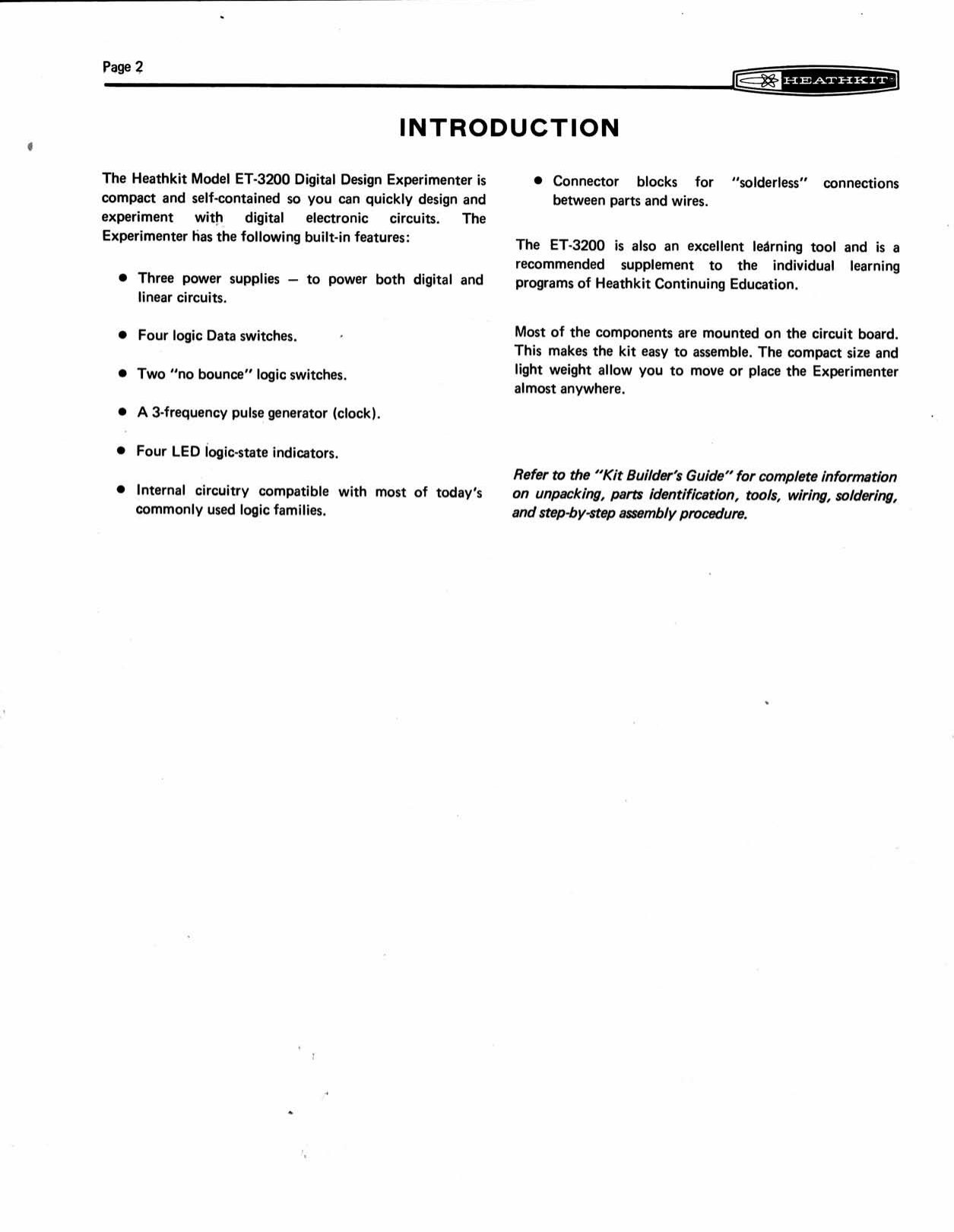
By Heath’s standards the ET-3200 was a small kit. Almost everything goes on one circuit board, there is one adjustment, and the test procedure uses nothing more than a voltmeter and two short pieces of wire. The manual’s introduction says as much: “Most of the components are mounted on the circuit board. This makes the kit easy to assemble” (ET-3200 manual, p. 2). For many buyers it was also a first kit. The Digital Techniques course was sold to technicians and engineers who might never have built a Heathkit, and the trainer was their introduction to Heath’s step-by-step method before the course began. This volume follows the 1975 manual in order and notes where the 1983 ET-3200B manual differs.
Heath’s general approach to its manuals (the check-off steps, the pictorials, the “Kit Builder’s Guide”) is described in the history dive’s volume on how a Heathkit manual works and is not repeated here.
3.1 What came in the box
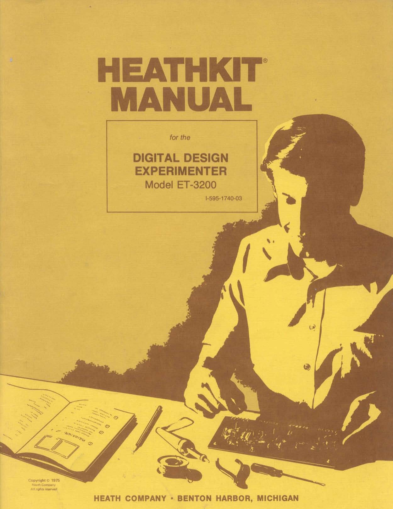
The 1975 manual runs to 45 numbered pages, plus parts-order cards and covers. Most large drawings are in a separate Illustration Booklet, which holds Pictorials 2-1 and 2-2, the chassis pictorials, the voltage chart and the fold-out schematic. General technique (unpacking, resistor colour codes, soldering) is in a separate Kit Builder’s Guide, which the assembly notes tell the builder to read first. The parts list runs over six pages and covers, in Heath’s categories:
- Resistors, ½ W, mostly 10 %, and two 1 % precision resistors (R17, 2000 Ω, and R18, 2250 Ω) for the tracking divider.
- Capacitors, from a 62 pF mica up to the three big filter electrolytics (two 1200 µF, one 2000 µF).
- Semiconductors: eight 1N4002 rectifiers, a 1N4149 and a 1N3017 zener, four LEDs, fifteen transistors (twelve MPSA20, three 2N4121, and the MJE181/MJE171 power pair), and four ICs (a µA7805, an NE555V and two SN7403N).
- Switches: seven slide switches and the rocker power switch.
- Solderless hardware: 21 small four-point connector blocks and one breadboarding socket “with connectors and vinyl strip”.
- IC sockets: two 14-pin and one 8-pin, so the three logic and timer ICs plug in.
- Mechanical parts: cabinet top and bottom, two heat sinks, the power transformer, line cord, fuse and clips, neon lamp and red lens, foam tape, silicone grease, and a plastic nut starter.
- An IC puller, supplied “so you can gently and easily lift the IC out” of the breadboard later.
Source: manual, Parts List, pp. 3–8.
The Assembly Notes give the main technical warning. Some foil areas on the board are small and closely spaced, so the builder must “use the utmost care to prevent solder bridges between adjacent foil areas”, use “only a minimum amount of solder”, and use “no larger than a 25-watt soldering iron with a small tip” (manual, p. 10). The same page carries the standard safety line about holding lead ends when cutting them so they cannot fly toward the eyes.
3.2 Stage 1: the circuit board
The first five pictorials populate the board from its component side, starting with the parts that sit lowest.
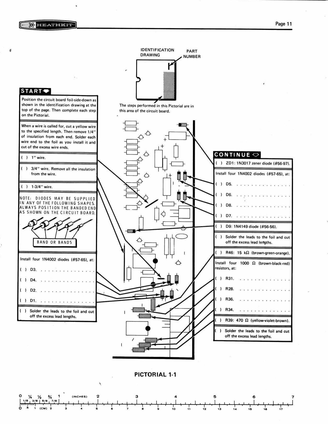
Pictorial 1-1: the zener diode ZD1, four of the eight 1N4002 rectifiers and a first group of resistors. The manual warns that “diodes may be supplied in any of the following shapes” and tells the builder always to position “the banded end as shown on the circuit board”.
Pictorial 1-2: most of the remaining resistors, including the four LED-driver groups, and the two precision resistors.
Pictorial 1-3: the IC sockets, the small capacitors, and then the ICs themselves. Heath shows how to find pin 1, straighten the pins, and line the pin-1 end up with “the half-moon mark on the circuit board”. The same page introduces the IC puller in case an IC ever has to come out again.
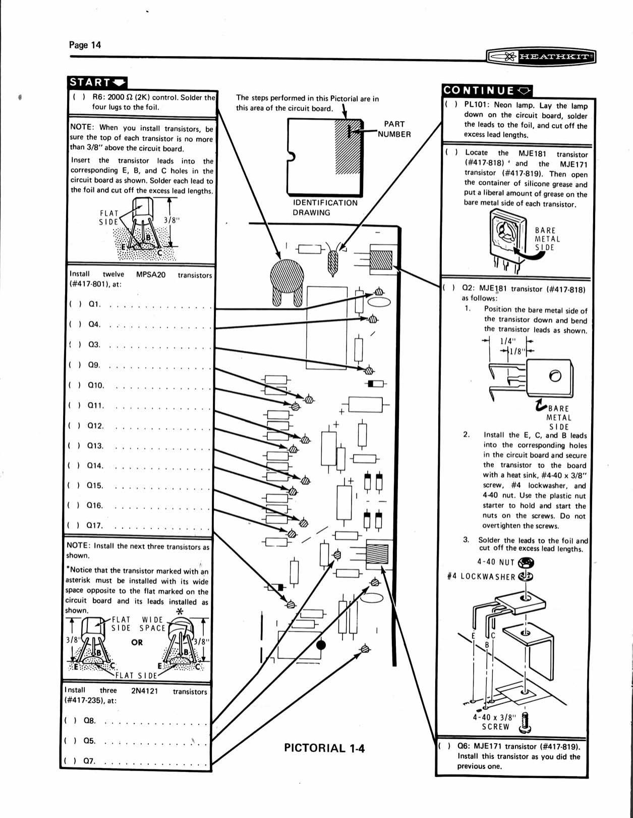
Pictorial 1-4 installs the transistors. The tops of the twelve MPSA20s must be “no more than 3/8” above the circuit board”. The three 2N4121s have their own warning: the transistor “must be installed with its wide space opposite to the flat marked on the circuit board”, which is easy to get backwards. The two power transistors, the MJE181 and MJE171, get “a liberal amount” of silicone grease on their metal faces. Each is laid flat, bent to fit, and bolted to the board through a small heat sink with a 4-40 screw, lockwasher and nut, which the builder starts with the plastic nut starter. The regulator control R6 and the neon pilot lamp PL101 go in at the same stage. The neon is laid flat on the board with its leads soldered to the foil.
Pictorial 1-5 mounts the µA7805, prepared the same way with grease and fitted with the large heat sink and a 6-32 screw.
3.3 Stage 2: the panel side
The ET-3200’s circuit board is also its front panel. The component side is silk-screened with the panel legends, and when the kit is finished the cabinet top covers only the strip of small components along the board’s upper edge (see the X-ray view in volume 2). The second stage fits the parts the user will touch.
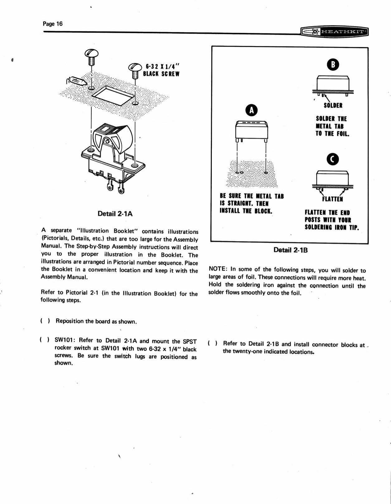
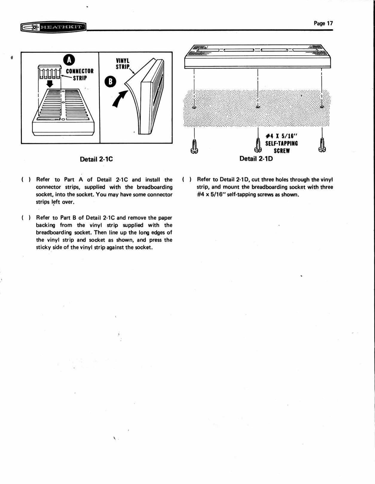
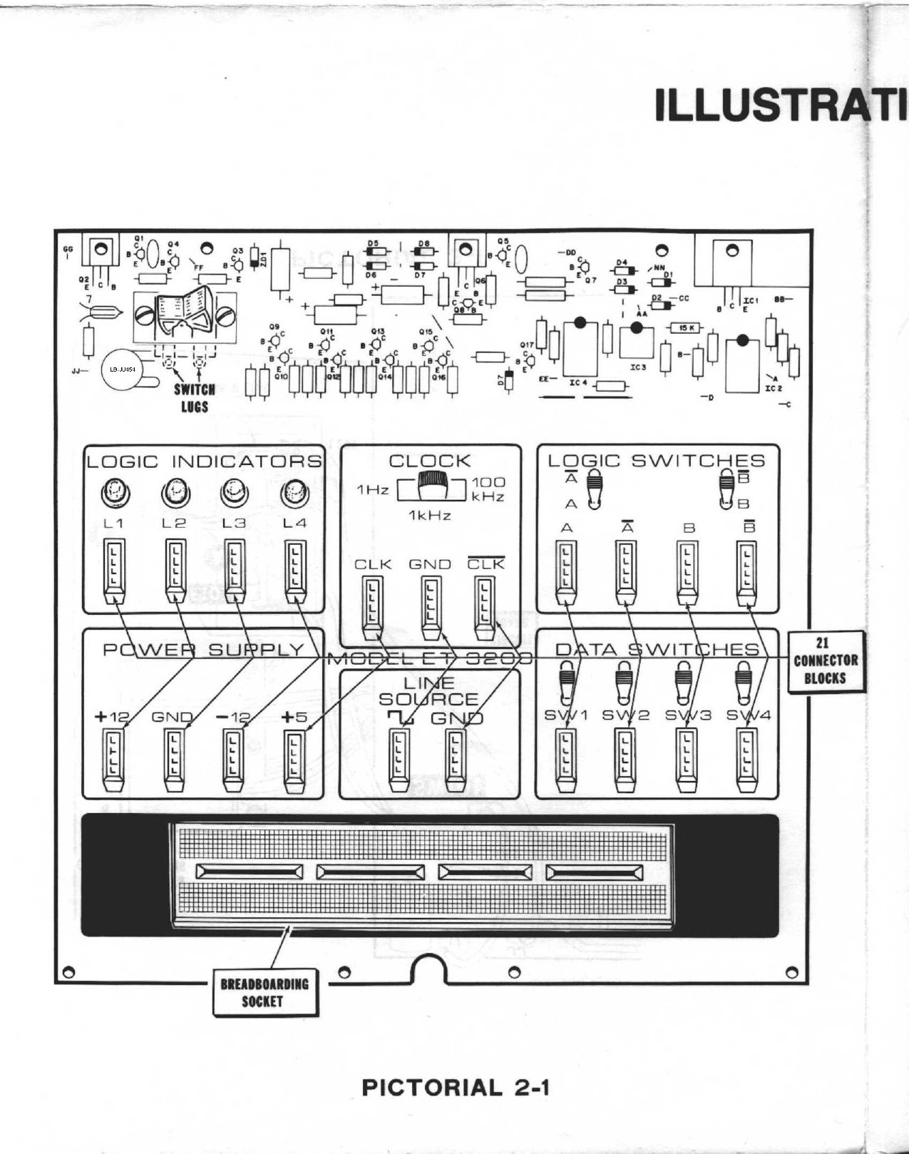
Pictorial 2-1 (in the Illustration Booklet) begins with the rocker power switch SW101, fastened with two black screws. Then come the 21 connector blocks. Each block has a metal tab that is soldered to a foil pad. The builder is told to make sure the tab is straight before installing the block, then to “flatten the end posts with your soldering iron tip” (Detail 2-1B). The flattening is a hot-staking step: the block’s plastic posts are melted over to lock it to the board. The breadboarding socket is assembled from parts: its contact strips are pushed into the moulded body (“you may have some connector strips left over”), a self-adhesive vinyl backing strip is pressed on, three holes are cut through the vinyl, and the socket is screwed down with three self-tapping screws.
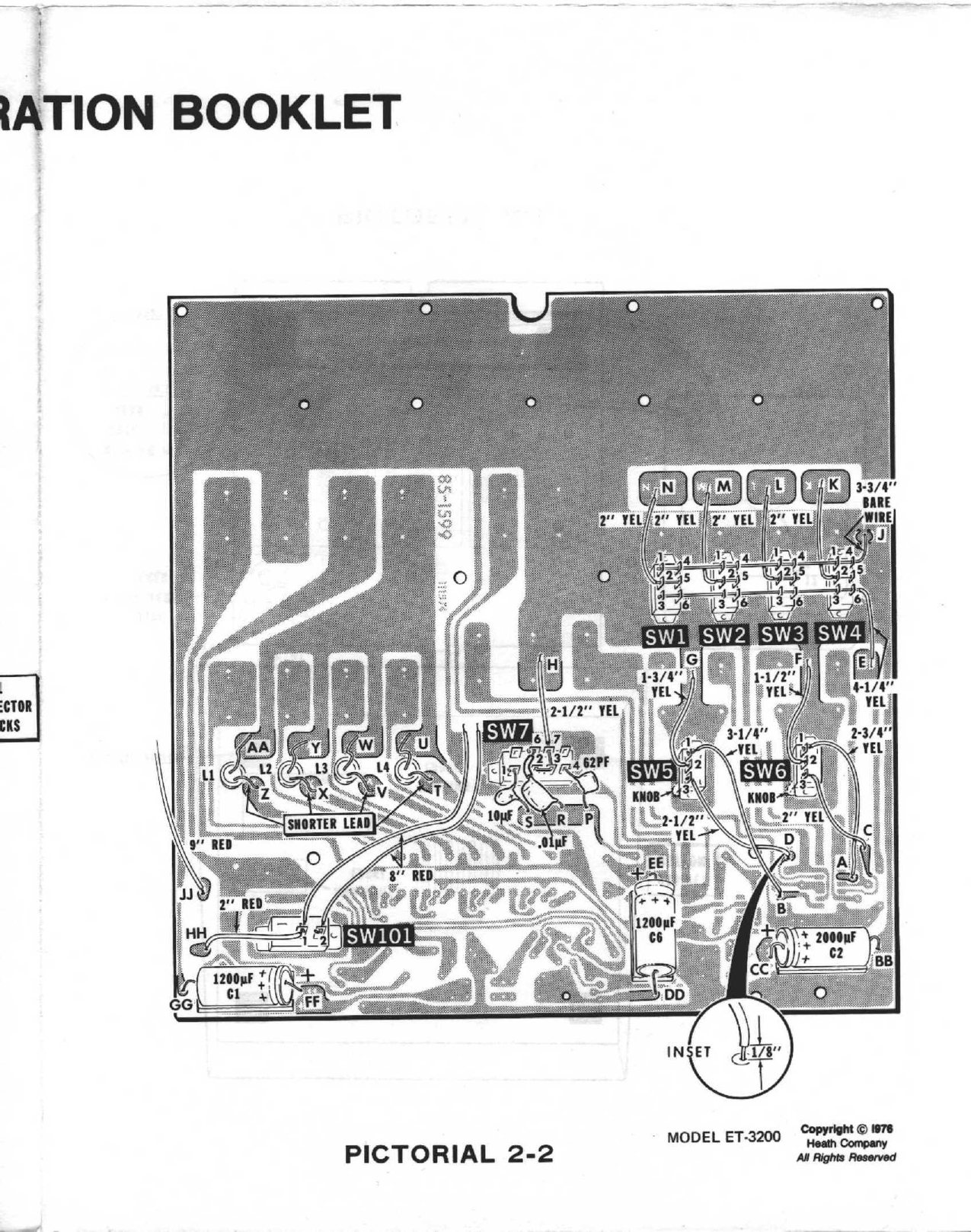
Pictorial 2-2 turns the board foil-side-up for the switches. Each slide switch is centred over its foil pattern and tacked by one tab with “only a small amount of solder at only one spot”. The builder then works the switch to check “that it works freely and that the switch knob does not rub against the circuit board” before soldering both tabs. The four DPDT data switches, the two spring-return SPDT logic switches (with knobs positioned as shown) and the three-position clock switch SW7 go in this way.
The LEDs go through the board from the panel side. The lead nearest each LED’s flat is cut to 5/8 inch. A plastic grommet is pushed into the hole, the LED pushed fully into the grommet, and a retainer ring pressed over it. The leads are then soldered flat to the foil on the back.
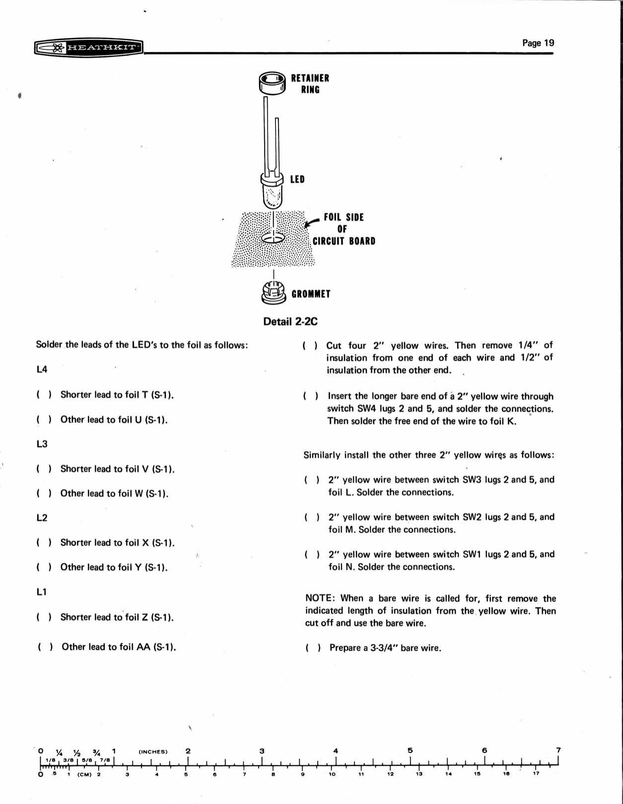
The rest of Pictorial 2-2 is point-to-point wiring on the foil side. A bare wire is threaded through lugs 4 and 1 of all four data switches to form their common bus. The three clock capacitors are soldered directly across the lugs of SW7: C9, the 10 µF tantalum, with its polarity marked; C10, the Mylar, with a sleeve on one lead; and C11, the 62 pF mica. Short yellow jumpers join the logic switches to the board, and red stranded wires are left long for the mains wiring. Two techniques appear here for the first time:
- Special solder points. On large ground areas, “portions of foil have been etched away so solder connections will not require as much heat” (Detail 2-2D). These are thermal reliefs, shown to the kit builder as a feature.
- Foam tape. Three strips of double-sided foam tape are stuck to the foil side, after the builder checks that there are “no solder bridges” under them. The three big electrolytics (C1, C6 and C2) sit on the tape with their leads cut to one inch.
3.4 Stage 3: the mains wiring
The chassis is the moulded cabinet bottom. The builder temporarily screws a six-lug terminal strip to a post and fits two fuse clips and the 3/16-A slow-blow fuse. The line cord is fed in through a hole, and a knot is tied in it 4¼ inches from the end to act as the strain relief. The two conductors are identified as the “smooth lead” and the “ribbed lead”, then twisted, tinned and wrapped under the terminal strip. The transformer is screwed down with its red and green leads uppermost.
The builder then chooses one of two sets of instructions, 120 V or 240 V, which connect the four primary leads to the terminal strip in parallel or in series. The manual prints the warning in capitals: “USE ONLY THE INSTRUCTIONS THAT AGREE WITH THE LINE VOLTAGE IN YOUR AREA” (manual, p. 23). In Final Wiring the secondary leads go into holes on the component side of the board (red pair to KK and LL, red-yellow to MM, green pair to AA and NN), and the switch and neon wires go to the terminal strip. Finally the terminal strip is moved into a box moulded into the cabinet bottom, and an insulating cover plate is screwed over it. The builder then writes “3/16-A, slow blow” on the fuse label on the cover.
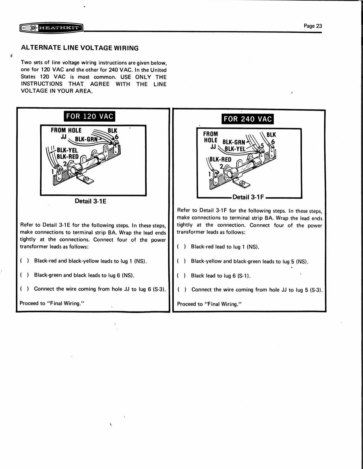
This mains arrangement dates the original ET-3200. It has a two-wire cord with no ground, a fuse reachable only by removing the cabinet, a knot for strain relief, and mains wiring protected only by a plastic cover inside a plastic box. By 1983 the ET-3200B had a three-wire cord with a relief plate, a panel-mounted fuseholder, a mains filter and a separate caution label (ET-3200B manual). Volume 6 discusses what this means for an owner of an early unit.
3.5 Stage 4: test and adjustment
The Test and Adjustments section runs with the board lying loose beside the cabinet bottom, mains connected. It begins with two precautions: put “an insulator (piece of cardboard, etc.) under switch SW101 so the switch lugs cannot touch your work surface”, and “do not touch the area marked high-voltage area”. The builder then plugs in, and the neon should light. If it does not, the builder is told to “push switch SW101 to the other position”. The rocker is unmarked, and the neon is the only way to tell on from off.
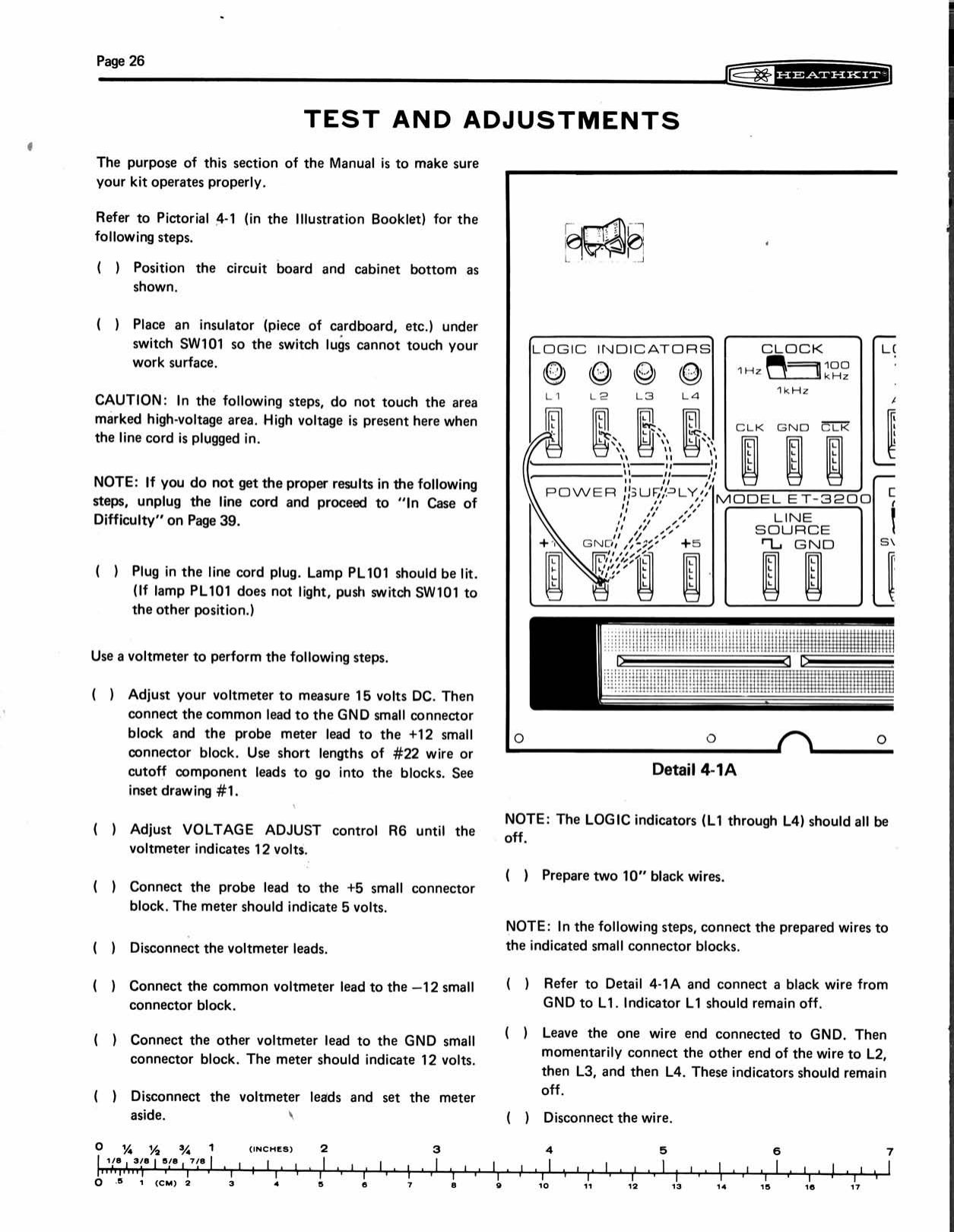
The only adjustment follows. With a voltmeter on the 15 V d.c. range between GND and +12, the builder turns the VOLTAGE ADJUST control R6 “until the voltmeter indicates 12 volts”. The +5 terminal should then read 5 V, and the −12 terminal 12 V with the polarity reversed. The manual advises using “short lengths of #22 wire or cutoff component leads to go into the blocks”, which is also the first time the builder uses the connector blocks.
The rest of the test uses two 10-inch black wires and the trainer’s own indicators, a small introduction to the way the trainer will be used:
- GND to each of L1–L4: every indicator stays dark.
- +5 to each of L1–L4 in turn: each lights.
- LINE SOURCE to L4: it lights (a 60 Hz square wave looks steady).
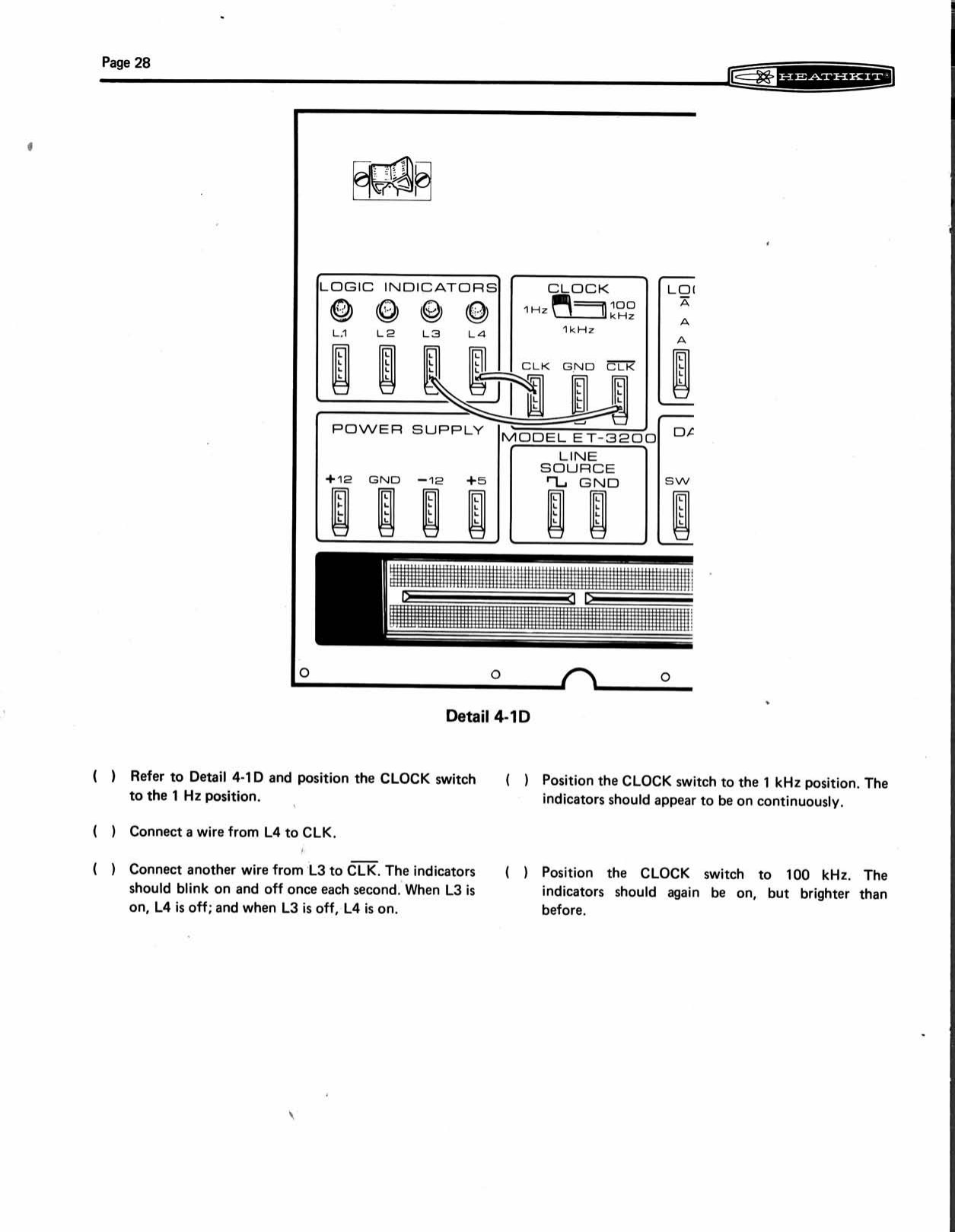
- Clock at 1 Hz, CLK to L4 and CLK̄ to L3: the two blink once a second, alternately.
- Clock at 1 kHz: both “appear to be on continuously”. At 100 kHz both are on, “but brighter than before”.
- The same two wires moved to logic switch A and Ā, then B and B̄: pushing each switch swaps which indicator is lit.
- Each data switch to L4: up lights it, down puts it out.
The brighter indicators at 100 kHz are a small lesson in their own right. The manual does not explain it. The likely cause is the drivers’ turn-off delay: at 100 kHz the saturated transistors’ storage time becomes a noticeable part of each cycle, stretching the on-periods and raising the average LED current.
3.6 Stage 5: final assembly
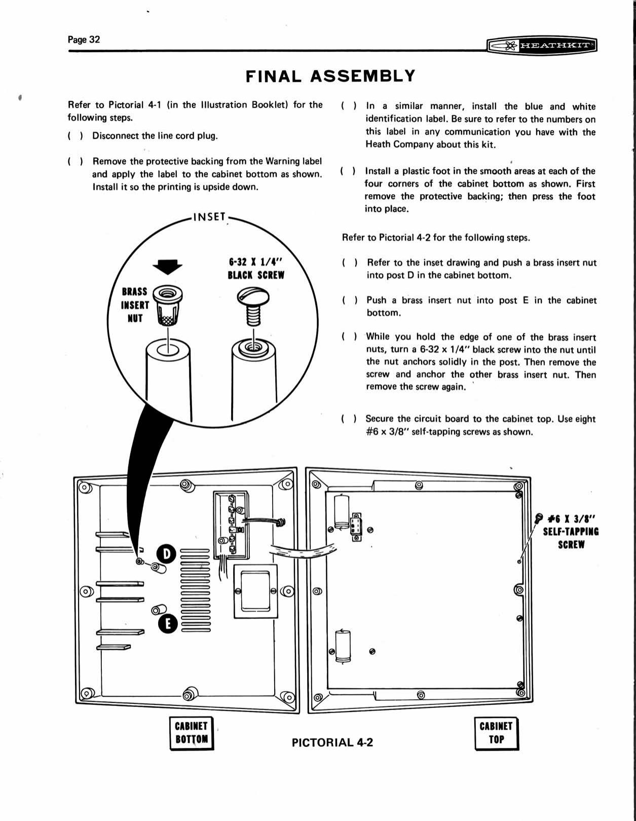
The last section closes the cabinet. The builder applies the warning label to the cabinet bottom “so the printing is upside down” (it reads correctly when the unit is turned over), then the blue-and-white identification label and four stick-on feet. Two brass insert nuts are pushed into posts in the cabinet bottom and anchored by threading a screw into each and removing it again. The board is fixed to the underside of the cabinet top with eight self-tapping screws, and the top to the bottom with two black machine screws and eight more self-tappers. The red lens is pushed into the pilot hole and the Heathkit badge stuck on. The section ends: “Use the remaining wire for your experiments.”
3.7 When it did not work
The “In Case of Difficulty” section is the standard Heath one, with a visual-test list and a troubleshooting chart. One sentence from it is often quoted across Heath manuals of the period: “About 90% of the kits that are returned to the Heath Company for repair do not function properly due to poor connections and soldering.” The chart is short because the circuit is. The supply faults point to specific transistors, as described in volume 2. An indicator that stays dark points to its pair of driver transistors. “Clock will not change frequency” points to SW7. “LED remains lit with no input” points to the driver (manual, pp. 39–40).
3.8 The 1983 manual
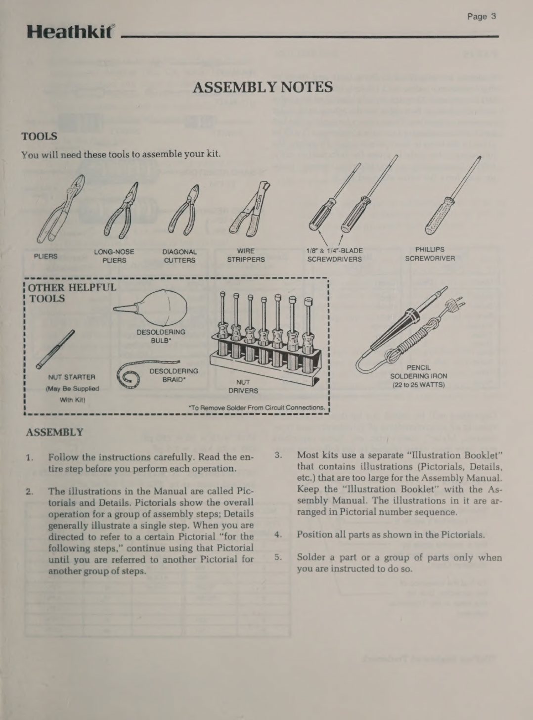
The ET-3200B manual (595-2936-06, 56 pages) follows the same order. It adds a front section, Assembly Notes, with drawings of the tools required: long-nose pliers, diagonal cutters, wire strippers, ⅛- and ¼-inch flat and Phillips screwdrivers, and a 22–25 W soldering iron. The “other helpful tools” are a desoldering bulb, desoldering braid and a nut starter. Its soldering instructions and its illustrations of good and bad joints are in the manual itself, rather than in a separate Kit Builder’s Guide. Its parts list is keyed to drawings of each part. It specifies black Phillips-head hardware throughout. The steps for the new parts are distinctive. The four 150 kΩ resistors are soldered on the foil side, by tinning the pads, laying the bent leads into the molten solder and holding them until it cools. The mains filter is wired point-to-point on the terminal strip, and the manual warns that C101 is rated for 120 V only (ET-3200B manual, pp. 3, 19, 24–25).
3.9 Build time
Neither the manuals nor the catalogues give an assembly time for the ET-3200, and no builder’s account with a time was found. The kit has fewer than a hundred components, most of them on the board, plus the switch and LED wiring and a short mains harness, so it was an evening or a weekend for a first-time builder, not a project of several weeks. The course materials assume the trainer is finished before Experiment 1 and give no time for it.
Sources
- Heath Company. Heathkit Manual for the Digital Design Experimenter, Model ET-3200, 595-1740-03, © 1975. Internet Archive. https://archive.org/details/Heathkit_ET-3200_Digital_Design_Experimenter
- Heath Company. ET-3200 Illustration Booklet (Pictorials 2-1 and 2-2, © 1976; schematic, © 1975). Internet Archive. https://archive.org/details/heathkit_et-3200 · https://archive.org/details/HeathkitET3200DigitalDesignExperimenterschematic
- Heath Company. Heathkit Manual for the Digital Design Experimenter, Model ET-3200B, 595-2936-06, © 1983. Internet Archive (DLARC). https://archive.org/details/manualsplus_11835
- Heathkit history dive, volume 8, “How a Heathkit Manual Works.” https://heathkit.fubsypoly.com/heathkit/vol-8/
Comments (0)