ET-3200 Digital Trainer · Volume 6
Restoration and Common Faults
An ET-3200 is one of the easiest Heathkits to bring back. It has no tubes, no high voltage beyond the mains, no alignment and no rare parts. The transistors are small-signal types, the three ICs that fail most often are in sockets, and the one adjustment takes a minute with a meter. The difficulties are mechanical and historical. Most surviving units spent years in school laboratories, and the parts that suffer are the ones students handled: terminal blocks, the breadboard, switches and the cabinet. The original 1975 version also has mains wiring that falls short of later practice. This volume covers safety first, then power-up, then faults by section, then replacement parts and modifications.
6.1 Safety: the mains side
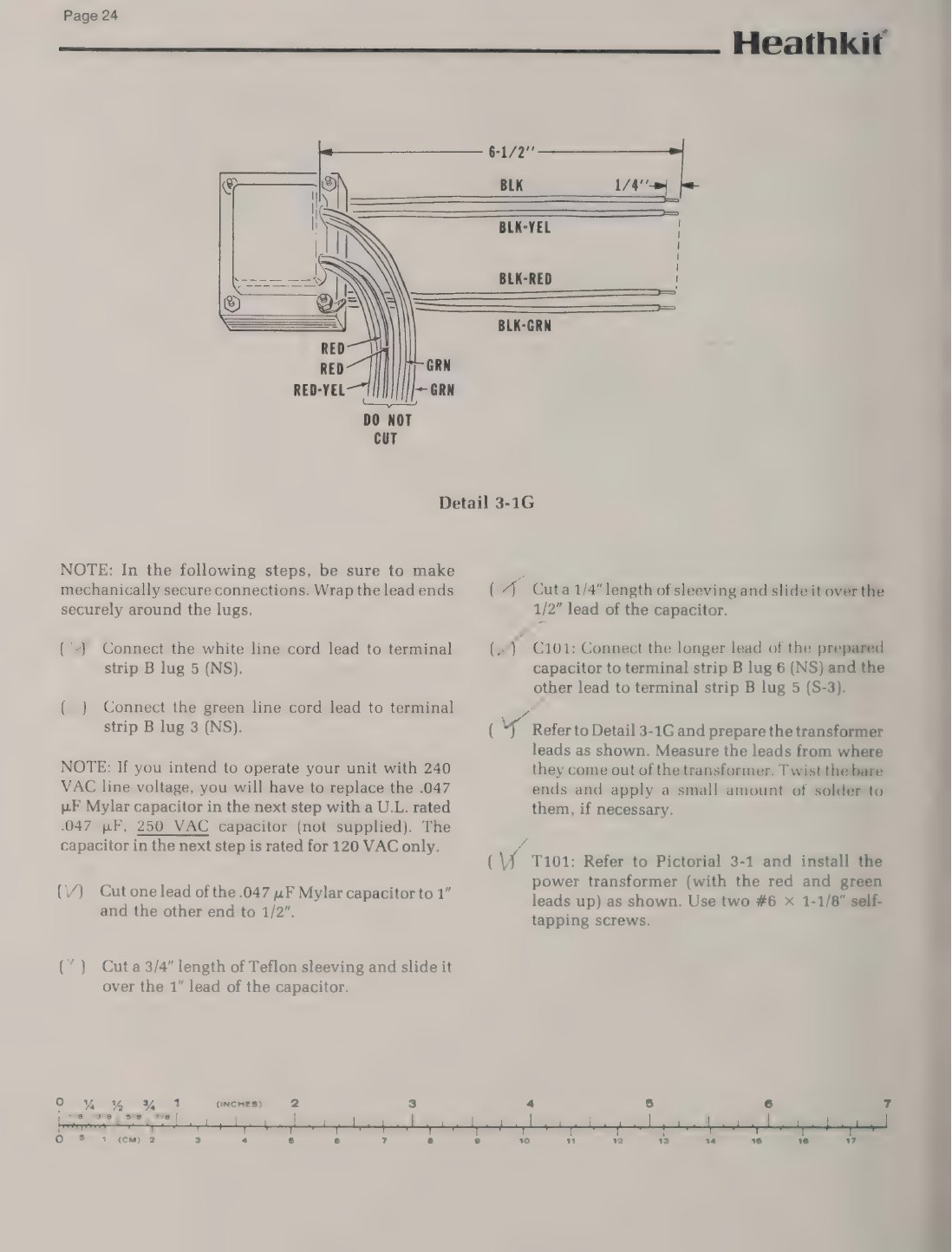
The ET-3200 has mains voltage on its circuit board. The power switch SW101 is mounted on the board. Two red wires carry the live side of the mains from the terminal strip up to the switch and back, and the manual’s test procedure warns: “do not touch the area marked high-voltage area. High voltage is present here when the line cord is plugged in” (ET-3200 manual, p. 26). The neon pilot and its 27 kΩ resistor are also on the board, connected across the transformer primary. Anyone who opens the cabinet must unplug the unit first. With the cabinet open, the upper left of the board (switch, neon, red wires) must be treated as live whenever the cord is in the wall.
The three versions differ in how the mains is handled:
- ET-3200 (1975): two-wire cord with no ground; a knot tied in the cord as its only strain relief; the fuse in clips on a terminal strip inside a box moulded into the cabinet bottom, under a screwed-on insulating plate. The fuse can be reached only by opening the cabinet (manual, pp. 21–24).
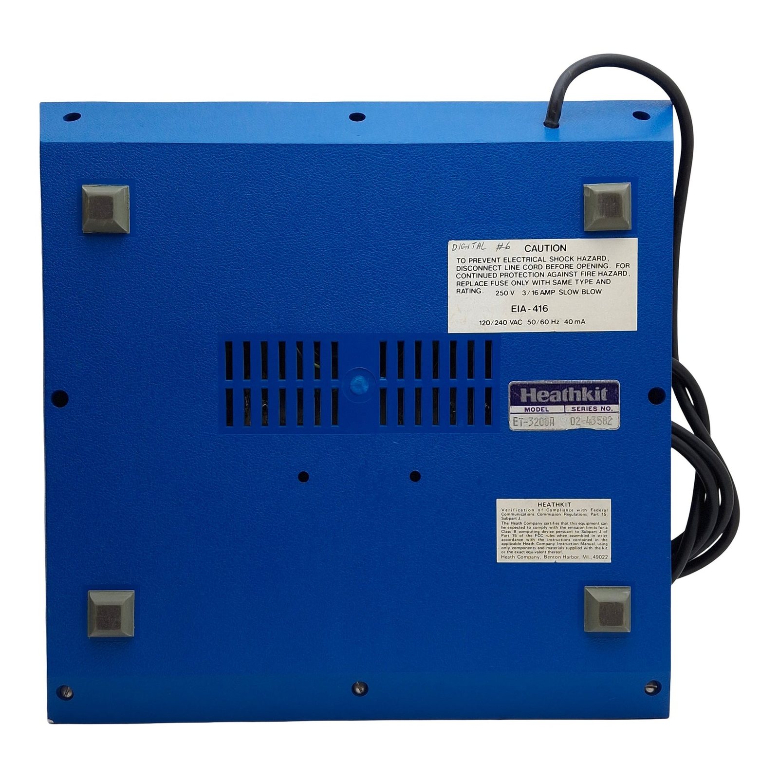
- ET-3200A (by 1981–82): the example examined has a three-pin plug and an FCC Class B label. Its internal details were not established.
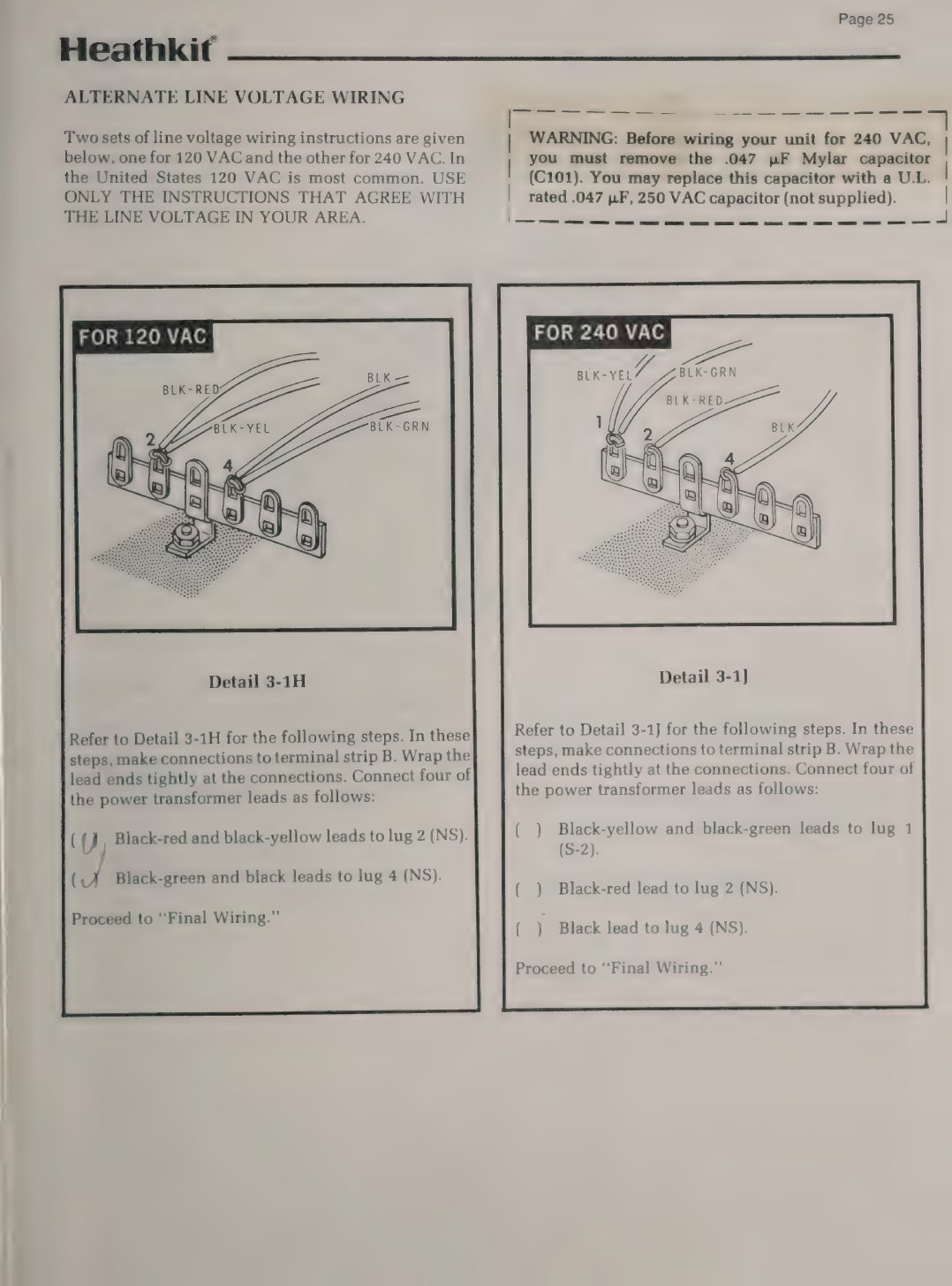
- ET-3200B (1983): three-wire cord with the green lead to a ground lug; a moulded relief plate; a panel fuseholder; a mains filter (toroid L101, a 0.047 µF Mylar capacitor across the line, and two 0.001 µF capacitors to ground) (ET-3200B manual, pp. 24–26).
In the original version, a cord that has hardened or cracked where it enters the cabinet should be replaced, and the knot is worth replacing with a proper strain-relief bushing. The cabinet is plastic and no metal is exposed on the outside, so the two-wire design is in effect double-insulated. It is safe only while the internal insulation (the terminal-strip cover plate, the switch insulator and the sleeving on the neon leads) is intact. Before the first power-up, check that the cover plate is present and screwed down, and that no strand of the mains wiring is loose inside the moulded box.
On the ET-3200B, look first at C101, the 0.047 µF capacitor across the mains. Heath supplied a Mylar part and warned that it “is rated for 120 VAC only”. Before wiring the unit for 240 V the builder had to replace it “with a U.L. rated .047 µF, 250 VAC capacitor (not supplied)” (ET-3200B manual, p. 25). A capacitor permanently across the mains is the part in any filter most likely to fail with smoke. The modern replacement is a safety-rated class X2 capacitor of the same value. On a 240 V unit, check that the builder actually made the change.
6.2 First power-up
A unit of unknown history should not simply be plugged in. A sequence that fits the circuit:
- Inspect. With the cabinet open, look for a swollen or leaking electrolytic among the three large filter capacitors (C1 and C6, 1200 µF; C2, 2000 µF) mounted on foam tape on the foil side. Look for cracked solder joints at the connector-block tabs and switch tabs, which take the most force, and for anything pushed into the breadboard or blocks that has shorted to the board.
- Check the fuse and its rating. It should be 3/16 A slow-blow. A larger fuse fitted by a previous owner defeats the only mains protection.
- Bring up the mains slowly. A variable transformer, or a series “dim-bulb” lamp of 25–40 W in the mains lead, limits the current if a filter capacitor or rectifier has shorted. The trainer draws at most 15 W, so a small bulb that glows briefly and then dims is the expected result.
- Measure the unregulated rails. Heath’s schematic gives about 12.4 V at C2 (the 7805 input) and ±18.6 V at C1 and C6, marked as load-dependent (schematic). Low readings with heavy a.c. ripple on a meter’s a.c. range, or on an oscilloscope, point to a failed filter capacitor.
- Measure and set the outputs. +5 V should be within a few per cent without adjustment. Set R6 for exactly +12.0 V, then check that −12 V follows, as it should because the negative regulator tracks the positive one.
- Run the functional test. The manual’s own procedure uses two jumper wires and checks every function in five minutes (manual, pp. 26–31). It is summarised in volume 3.
6.3 Faults by section
6.3.1 Power supplies
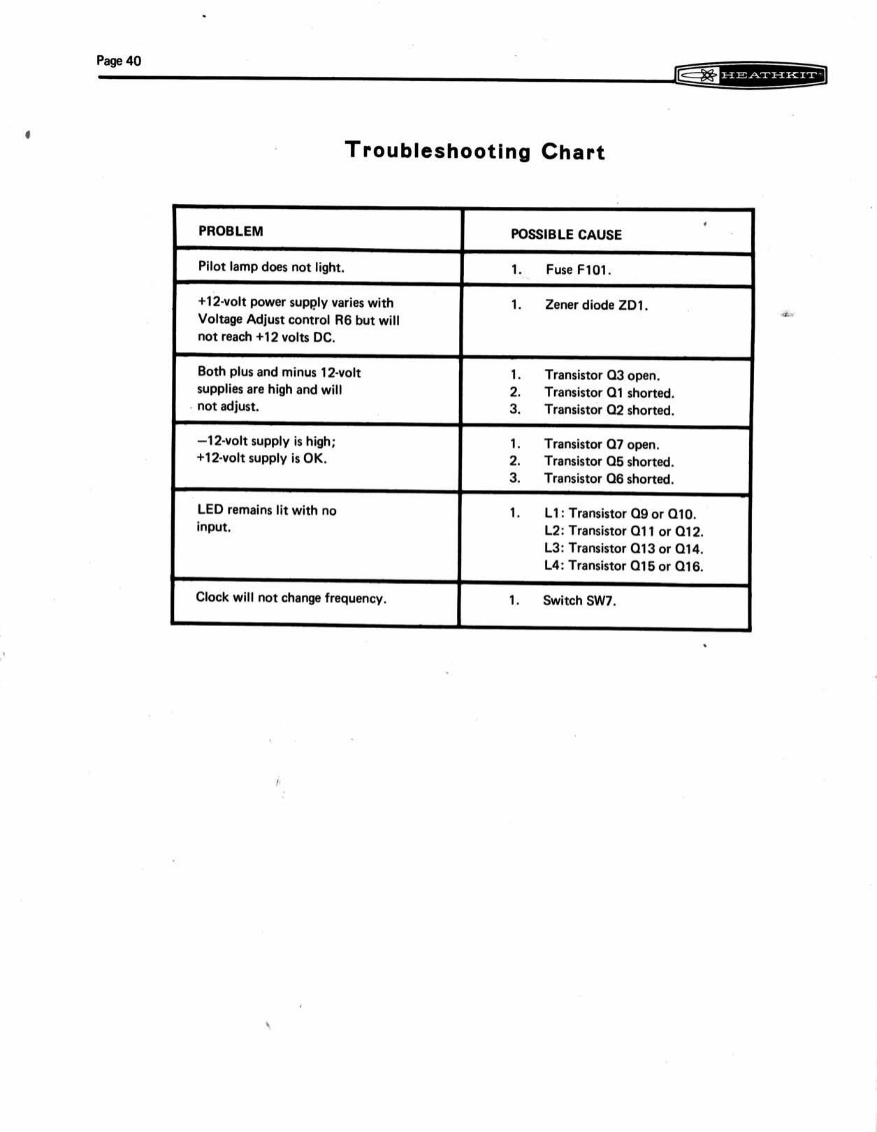
The manual’s Troubleshooting Chart already gives the common supply faults, and the circuit explains them (manual, p. 40; circuit in volume 2):
Table 1 — The manual's Troubleshooting Chart already gives the common supply faults, and the circuit explains them ([manual, p. 40](https://archive.org/details/HeathkitET-3200DigitalDesignExperimenter); circuit in [volume 2](https://heathkit.fubsypoly.com/et-3200-digital-trainer/vol-2/))
| Symptom | Likely cause |
|---|---|
| +12 V varies with R6 but will not reach 12 V | zener ZD1 (1N3017) |
| +12 and −12 both high, will not adjust | Q3 open, or Q1 or Q2 shorted |
| −12 V high, +12 V correct | Q7 open, or Q5 or Q6 shorted |
| +5 V low or dropping out under load | 7805 overheating (poor heat-sink contact, dried grease) or C2 failed |
| All rails low, heavy ripple | filter capacitors C1, C2, C6 |
Two faults are specific to age. The 7805 runs hot by design, dissipating up to about 3.7 W at full load (volume 2). The silicone grease under its heat sink will have dried after decades, so it is worth removing the regulator, cleaning both faces and regreasing, or fitting a thermal pad. The power transistors Q2 and Q6 are greased and bolted the same way and deserve the same treatment. The filter capacitors date from the 1970s or 1980s. Their values are not critical, and the ET-3200B’s substitution of 1000 µF and 2200 µF for 1200 µF and 2000 µF shows how much latitude Heath allowed. Modern 105 °C parts of the same voltage rating and similar values are a sound replacement. They must be refitted on the foam tape, with leads kept short, as in the original.
6.3.2 Clock
The Troubleshooting Chart has one entry for the clock, “Clock will not change frequency”, and points to the switch SW7. Two other failures are worth checking. C9, the 10 µF tantalum that sets the 1 Hz rate, is mounted on the switch lugs. Tantalum capacitors of the period can fail short, which stops the clock on the 1 Hz setting only. A low-leakage 10 µF electrolytic or a modern tantalum is a direct replacement, fitted with its positive lead to the same foil. At 100 kHz the frequency depends on the 62 pF mica C11 and on stray capacitance (volume 2), so a clock reading 80 or 120 kHz is within Heath’s ±20 % specification and is not a fault. The 555 and the two 7403s are in sockets, so substituting a known-good IC is the quickest test.
6.3.3 Logic indicators
An indicator that will not light when its input is taken to +5 V points to its driver pair (L1: Q9/Q10; L2: Q11/Q12; L3: Q13/Q14; L4: Q15/Q16). An indicator that stays lit with nothing connected also points to the driver, most often a leaky second transistor, and is listed in the chart as “LED remains lit with no input”. An indicator that glows faintly with a long, unconnected jumper wire in its terminal is not faulty. The input impedance is high and an open wire picks up enough signal to turn it partly on. That may be why Heath added the 150 kΩ base resistors in the ET-3200B (volume 2). Adding the same resistors to an original unit, soldered between each Q9/Q11/Q13/Q15 base and ground on the foil side as the ET-3200B manual shows, is a reversible improvement.
6.3.4 Switches
The seven slide switches are open-frame types soldered by their tabs to the board, and forty-year-old contacts oxidise. Intermittent data switches, or logic switches that give a double state change, respond to contact cleaner worked in by operating the switch repeatedly. The two spring-return logic switches carry a spring that tires. A logic switch that does not return fully to rest leaves its latch in the wrong state, and the fix is a replacement switch of the same type. Because the switches are soldered by their mounting tabs, desolder both tabs completely before pulling a switch. Levering it out lifts the pads.
6.3.5 Terminal blocks and breadboard
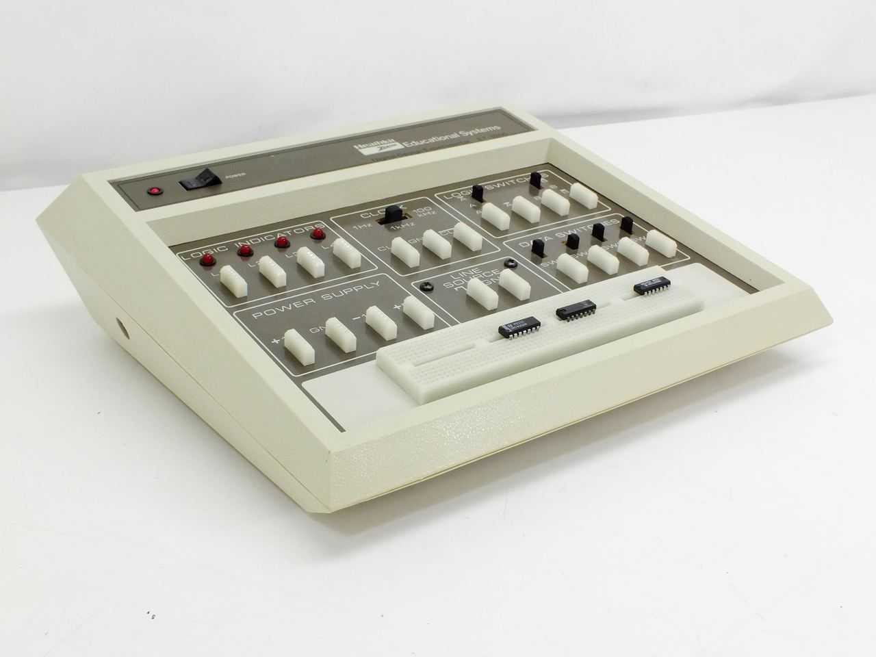
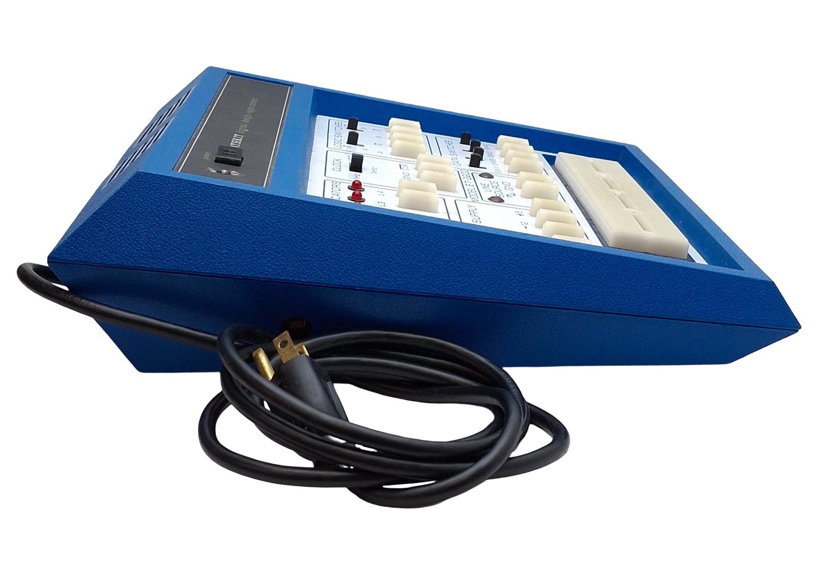
The 21 small connector blocks (Heath 432-874) are the ET-3200’s weakest parts. Each is held by one soldered tab and two hot-staked plastic posts (volume 3). Years of wires being pushed in and pulled out can break the posts, and a loose block then works its tab solder joint until it cracks, or comes away altogether. The blue ET-3200A illustrated in volume 1 has lost both the L1 and L2 blocks. Heath’s part is long out of production, and no exact modern equivalent was identified. The practical source is a donor unit. A cracked tab joint can be resoldered and a loose block glued, but the hot-staked posts cannot be restored.
The breadboarding socket (Heath 432-880) is a standard solderless breadboard strip of the period: 128 five-contact strips arranged as 64 pairs, one of each pair on either side of a centre channel, taking wire up to #20. Its contacts lose tension after heavy use and give intermittent connections. Hook-up wire or component leads thicker than #20 (0.032 in), which the manual prohibits, spring the contacts permanently. The socket is screwed down through its vinyl backing (volume 3). It can be replaced with any modern solderless breadboard of similar length, with the new one’s own adhesive backing covering the old screw holes or new holes drilled to suit. The trainer’s electrical design is unaffected.
6.3.6 Pilot lamp
The original’s neon pilot (PL101) with its 27 kΩ resistor is wired across the transformer primary. Neon lamps of that kind darken with age and eventually fail to strike. Because the unit is otherwise silent, a dead pilot matters. The test procedure itself relies on the neon to show which way the unmarked rocker is set. A replacement neon with an integral resistor is the like-for-like repair. The ET-3200B’s answer was a low-voltage LED pilot (D11) with an 820 Ω, ½ W resistor from the low-voltage side (ET-3200B manual). That is a reasonable modification for an original unit, and it takes the pilot off the mains.
6.3.7 Cabinet
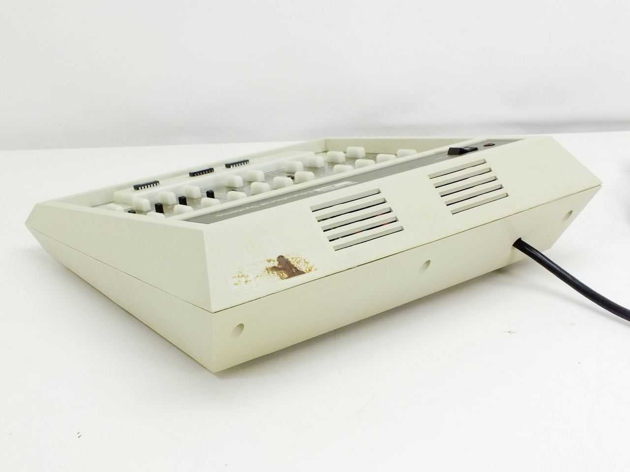
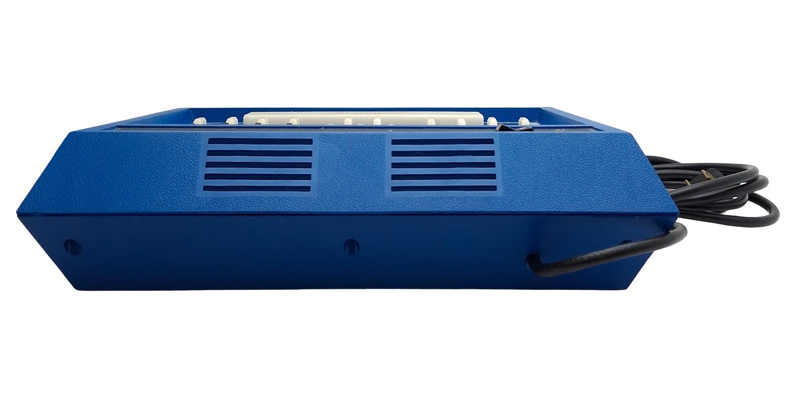
The cabinet top and bottom are moulded plastic, and the top has the nameplate strip and panel window moulded in. Cracks at screw bosses and broken corners are the usual damage. The two brass insert nuts in the bottom posts can pull out if the top screws are overtightened. They can be reset with epoxy. Adhesive labels and school inventory tags often cover the panel. The panel legends are silk-screened on the circuit board itself (volume 3), so cleaning it with anything stronger than mild detergent risks removing the lettering.
6.4 Replacement parts
The ET-3200’s semiconductors are general-purpose types. The substitutions below are standard equivalents by function. For every transistor, the pinout of the replacement must be checked against the board rather than assumed. Heath’s own note on the 2N4121, that it goes in with “its wide space opposite to the flat marked on the circuit board”, shows that the board’s layout does not follow one standard pattern.
Table 2 — Replacement parts
| Original | Function | Substitute | Notes |
|---|---|---|---|
| µA7805 (442-54) | +5 V regulator | any 7805 (LM7805, L7805) in TO-220 | regrease; same pinout |
| SN7403N (443-54) | open-collector NAND | 74LS03 | same pinout and open-collector outputs; socketed |
| NE555V (442-53) | clock | NE555 | a CMOS 555 changes the 100 kHz rate; keep a bipolar part |
| MJE181 / MJE171 (417-818/-819) | ±12 V pass | BD139 / BD140 or similar complementary TO-126 pair | limit is about 130 mA, so current rating is not critical; check E-C-B order |
| MPSA20 (417-801) | general NPN | 2N3904 or similar small-signal NPN | check pinout |
| 2N4121 (417-235) | general PNP | 2N3906 or similar small-signal PNP | check pinout against the board’s flat marking |
| 1N3017 (56-97) | 7.5 V, 1 W zener | 1N4737A | same voltage and power |
| 1N4149 (56-56) | clamp diode | 1N4148 | |
| 1N4002 (57-65) | rectifiers | 1N4002 to 1N4007 | |
| 1200 µF 30 V, 2000 µF 15 V electrolytics | filters | 1000–2200 µF, 35 V and 25 V, 105 °C | the ET-3200B used 1000 and 2200 µF |
| 10 µF tantalum (C9) | 1 Hz timing | 10 µF tantalum or low-leakage electrolytic | observe polarity |
| 3/16 A slow-blow fuse (421-31) | mains fuse | 3/16 A (0.187 A) time-delay | do not upsize |
Heath’s part numbers are from the ET-3200 manual’s Parts List. Data Professionals, the Heath-owned business that sells paper reprints of Heath manuals, is the source for a printed manual (history dive, volume 7).
6.5 Modifications
No period modification kit for the ET-3200 appears in the Heath catalogues examined, and no widely circulated owner modification was found. The design has little that needs fixing. The changes Heath made itself in the A and B versions (volume 2) are the best guide for an original unit:
- LED pilot in place of the neon, taken from a low-voltage rail (the ET-3200B used an 820 Ω resistor).
- 150 kΩ base resistors on the four indicator inputs, to hold an open input firmly off.
- Better mains hardware: a new cord with a real strain relief, and optionally a panel fuseholder so the fuse can be changed without opening the unit.
Owners who use the trainer as a general bench tool sometimes want more indicators or switches than four of each. These are best added on a separate board plugged into the breadboard, which leaves the trainer original.
Sources
- Heath Company. Heathkit Manual for the Digital Design Experimenter, Model ET-3200, 595-1740-03, © 1975: Test and Adjustments, In Case of Difficulty, Troubleshooting Chart, Parts List. https://archive.org/details/Heathkit_ET-3200_Digital_Design_Experimenter
- Heath Company. ET-3200 schematic, © 1975. https://archive.org/details/HeathkitET3200DigitalDesignExperimenterschematic
- Heath Company. Heathkit Manual for the Digital Design Experimenter, Model ET-3200B, 595-2936-06, © 1983. https://archive.org/details/manualsplus_11835
- Next Day Automation, sales listing SB-202541 (ET-3200A photographs). https://www.nextdayautomation.com/products/used-heathkit-et-3200-a-digital-design-experimenter-laboratory-breadboard-120-240vac
- Recycled Goods, sales listing (grey ET-3200 photographs). https://recycledgoods.com/heathkit-et-3200-digital-design-experimenter/
- Heathkit history dive, volume 7, “After the Kits.” https://heathkit.fubsypoly.com/heathkit/vol-7/
Comments (0)