GR-2000 Color Television · Volume 2
How It Works
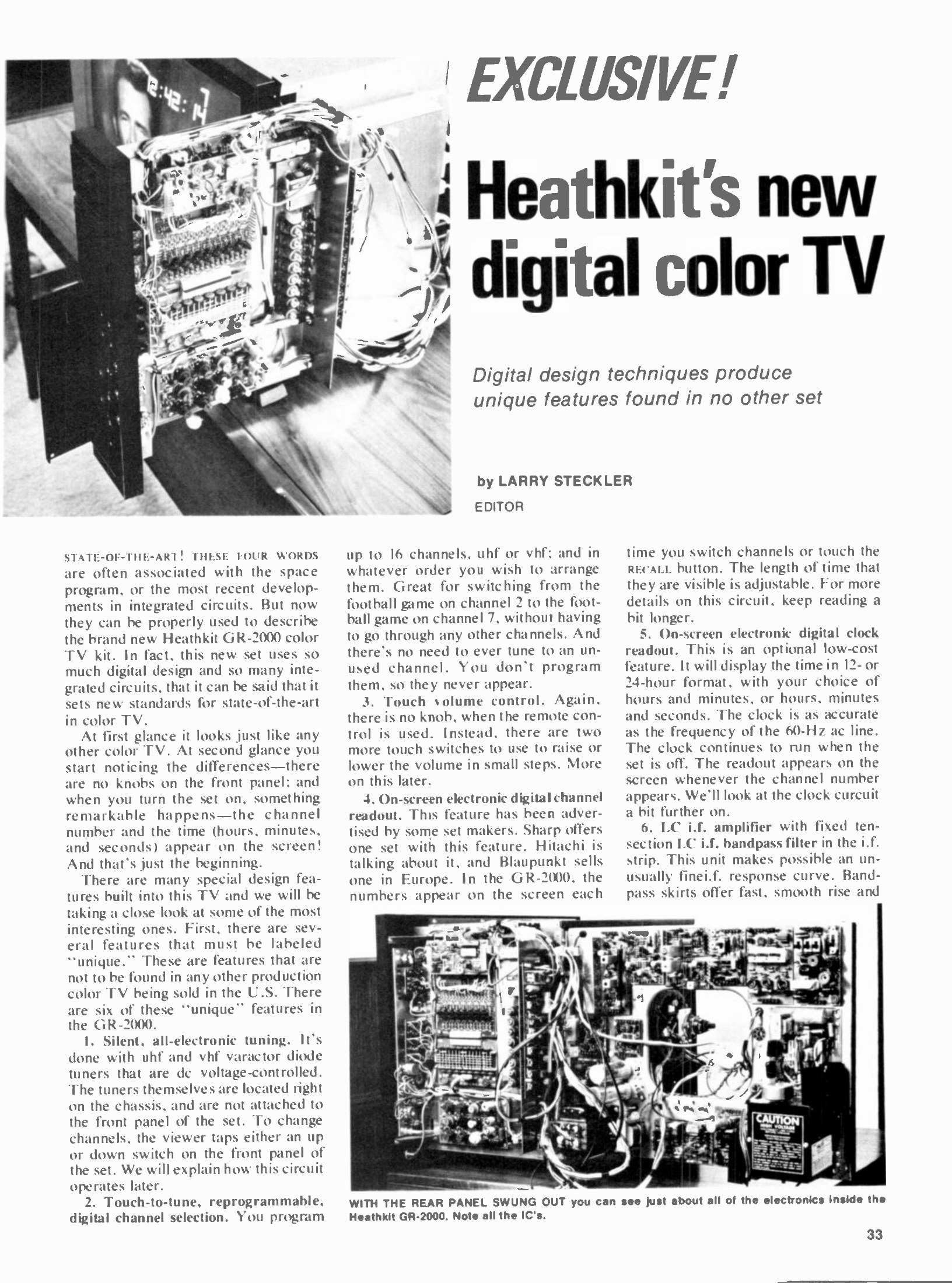
A colour television of 1974 was a hard machine to build at home for one reason above all: it had to be aligned. Traps in the intermediate-frequency strip had to be tuned against a sweep generator and a marker generator, the three beams had to be made to land on their own phosphor dots, and the three rasters had to be made to lie on top of one another across the whole screen. Heath’s answer, taken as early as the 1963 GR-53 and carried through to the GR-2000, was to remove the need for external instruments altogether: the critical filters left the factory aligned and sealed, and the instruments needed for the rest — a dot generator and a meter — were built into the television and switched in from the front panel. The GR-2000 went further than any set before it by doing the tuning, and the display of what it was tuned to, in digital logic.
This volume follows the signal through the set, then takes the three digital subsystems — channel selection, on-screen character generation and the clock — stage by stage. The descriptions rest on the two contemporary engineering accounts of the chassis, Larry Steckler’s in Radio-Electronics of February 1974 and the Popular Electronics test report of April 1974, together with the surviving Heath manuals for the closely related GR-2001 and for the GRA-2000-1 clock.
2.1 The receiver proper
2.1.1 Tuners
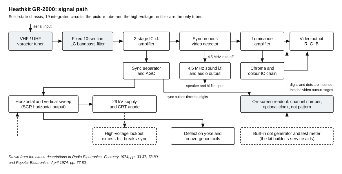
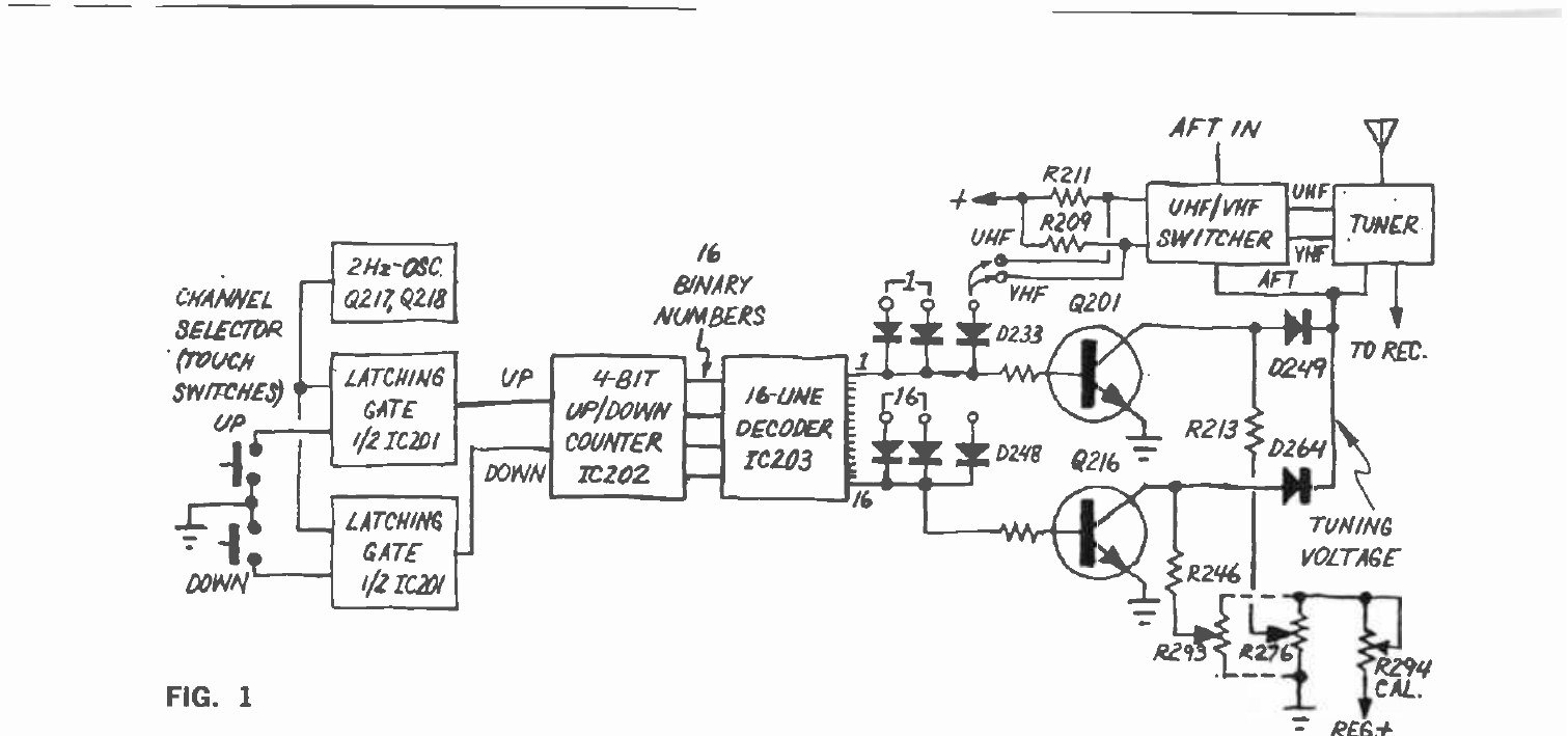
Both tuners are varactor types. Instead of switching coils with a turret, each tuned circuit contains a varactor diode whose capacitance follows a d.c. control voltage, so a channel is selected by applying the right voltage. The tuners sit on the chassis rather than behind the front panel, because nothing mechanical connects them to it. Automatic fine tuning is added to the same control line: the a.f.t. voltage is combined with the channel voltage in a VHF/UHF switcher module, which also converts the tuner to UHF operation when the selected channel calls for it. Popular Electronics describes the mechanism: when a UHF channel is programmed, strapping on the channel-selection board develops a voltage drop across R211, and the switcher module applies the correct voltage to the tuner for that selection (Popular Electronics, April 1974, p. 77).
2.1.2 The fixed i.f. filter
The intermediate-frequency amplifier is the part of the set that most impressed the reviewers, and the part that made an un-aligned kit television credible.
In a conventional 1974 colour receiver, selectivity is produced by tuned LC circuits distributed through the i.f. amplifier and by narrow traps — one at 39.75 MHz to reject the picture carrier of the channel above, another at 47.25 MHz for the sound carrier of the channel below. Those traps drift as components age, and they need instruments to set.
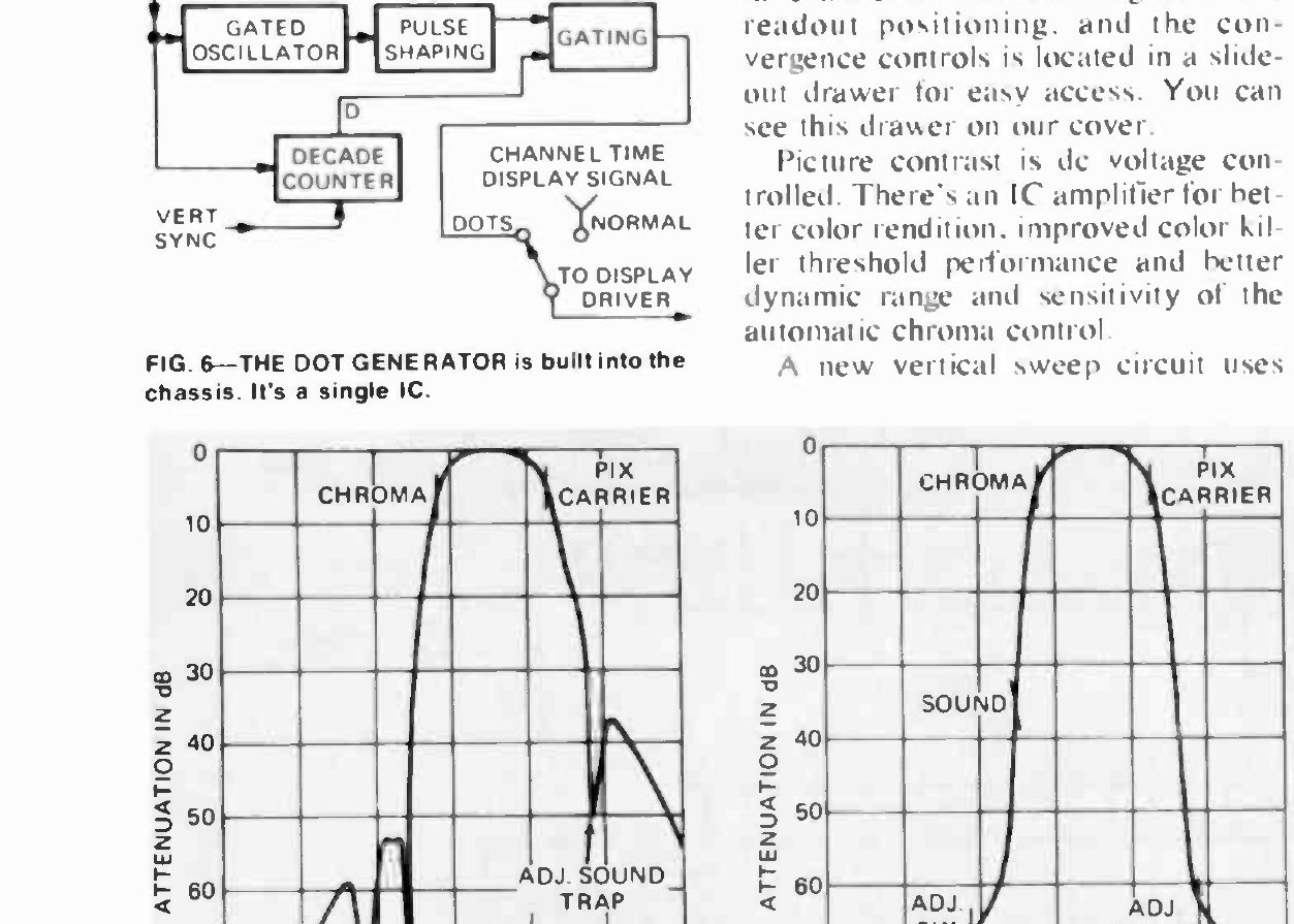
The GR-2000 replaced the whole arrangement with a single ten-section LC bandpass filter, described by Popular Electronics as “a predistorted transitional gaussian design”, computer-designed, sealed in a double-shielded enclosure and aligned at the factory. It is the only response-shaping element in the strip. Radio-Electronics published both response curves side by side and measured the result: adjacent-channel carriers a minimum of 60 dB down, and skirts steep enough that “the 10-to-15-dB ‘comeback’ problem typical of the conventional trap is nonexistent”. The magazine added that this was “the first set we have seen that includes a filter-type i.f.”, and drew the consequences: better performance, easier assembly because no instrument alignment is required, and a picture that stays as good as it started because there is nothing to drift.
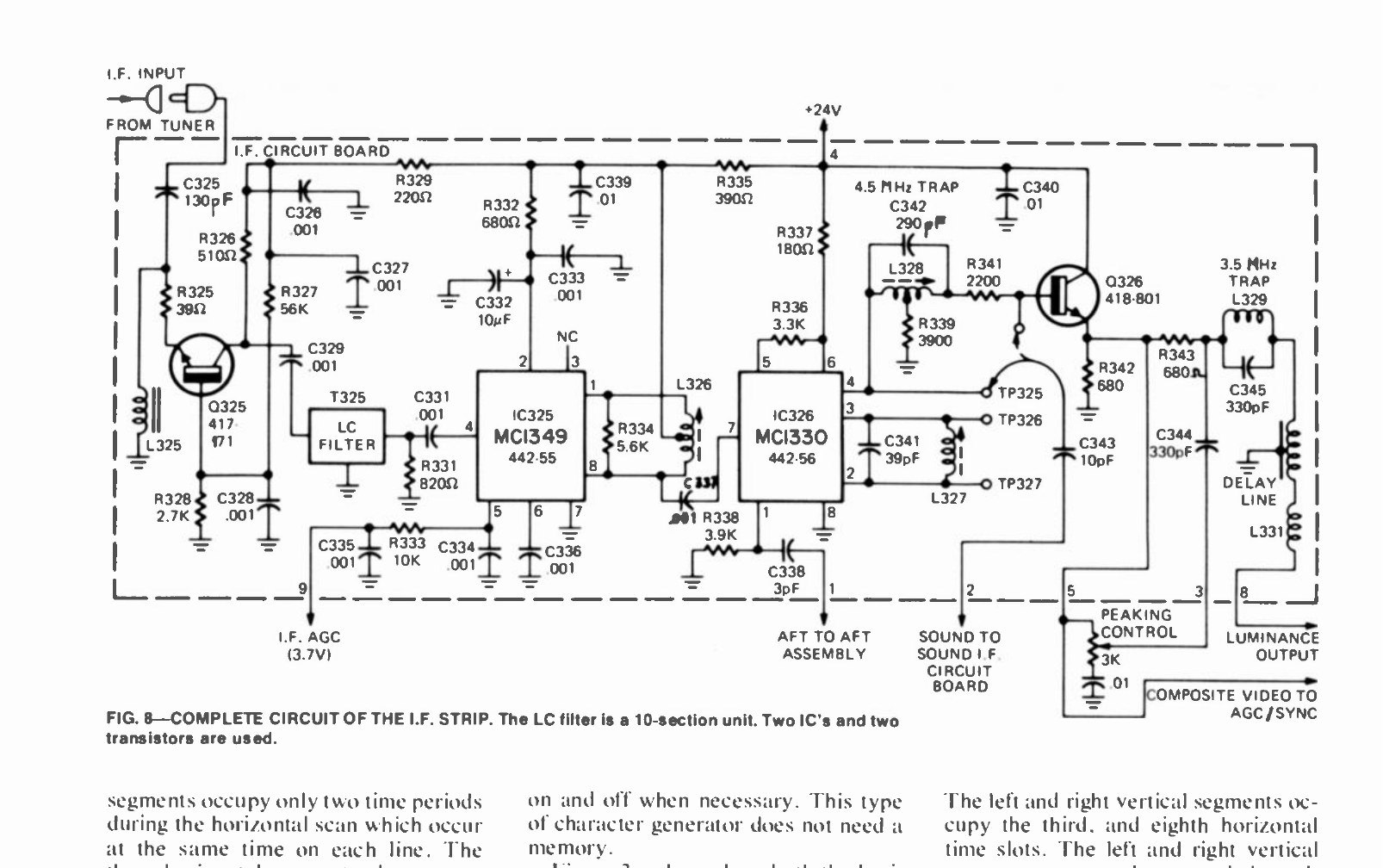
Around the filter the circuit is conventional in outline and integrated in execution. The tuner’s i.f. output is coupled into the filter through Q325, a common-base stage that both provides gain and presents a constant impedance to the tuner and the filter while isolating them. The filter feeds a two-integrated-circuit amplifier chain — an MC1349 gain block and an MC1330 synchronous detector in the circuit as published — which supplies gain, synchronous video detection, an a.f.t. output and a choice of high- or low-impedance composite video outputs. The transformer between the two ICs is broadly tuned, so it can be set without special instruments. The 4.5 MHz intercarrier sound signal is taken from the low-impedance output, with a 4.5 MHz trap feeding emitter follower Q326 which drives the a.g.c. and chroma circuits.
2.1.3 Video, chroma and sweep
From the detector the luminance signal runs through an amplifier with d.c.-controlled contrast — the contrast control varies a voltage rather than passing video, which keeps interference out of the picture — and into the video output stages. The chroma chain is built around integrated circuits: an IC colour amplifier for “truer colors”, an IC colour oscillator with automatic phase control for stable tints, and an IC automatic gain control for sensitivity, selectivity and noise rejection. Automatic chroma control, a colour killer and adjustable video peaking are all in the chassis.
The vertical sweep circuit uses complementary power transistors, which allowed Heath to delete the vertical output transformer and with it, as Radio-Electronics noted, “its magnetic and linearity problems”; the magazine judged the resulting interlace “near perfect”. The horizontal output assembly develops the 26,000-volt anode supply for the picture tube. A restorer who has had a GR-2000 chassis apart describes the sweep as an RCA-derived design with SCR horizontal output (VideoKarma thread, “Heathkit GR-2000 Solid State Color TV”); Heath’s own catalogue spec for the family’s earlier 25-inch set lists two SCRs in the chassis, which is consistent, but no Heath document consulted here states it for the GR-2000 outright.
One circuit on the horizontal oscillator board exists purely for safety and deserves naming here because it is invisible until it misbehaves. A lockout circuit monitors the high voltage; if it rises above the permitted figure, the circuit pulls the horizontal oscillator out of lock and the picture breaks into diagonal lines. A set that will not hold horizontal sync is therefore telling its owner to look at the high-voltage assembly, not at the hold control. The GR-2001 manual gives a functional test for it, and warns that the resistor used in the test gets very hot (GR-2001 assembly manual, Book Three, p. 3-29). Its purpose is discussed with the X-radiation rules in the restoration volume.
2.1.4 The picture tube and its shield
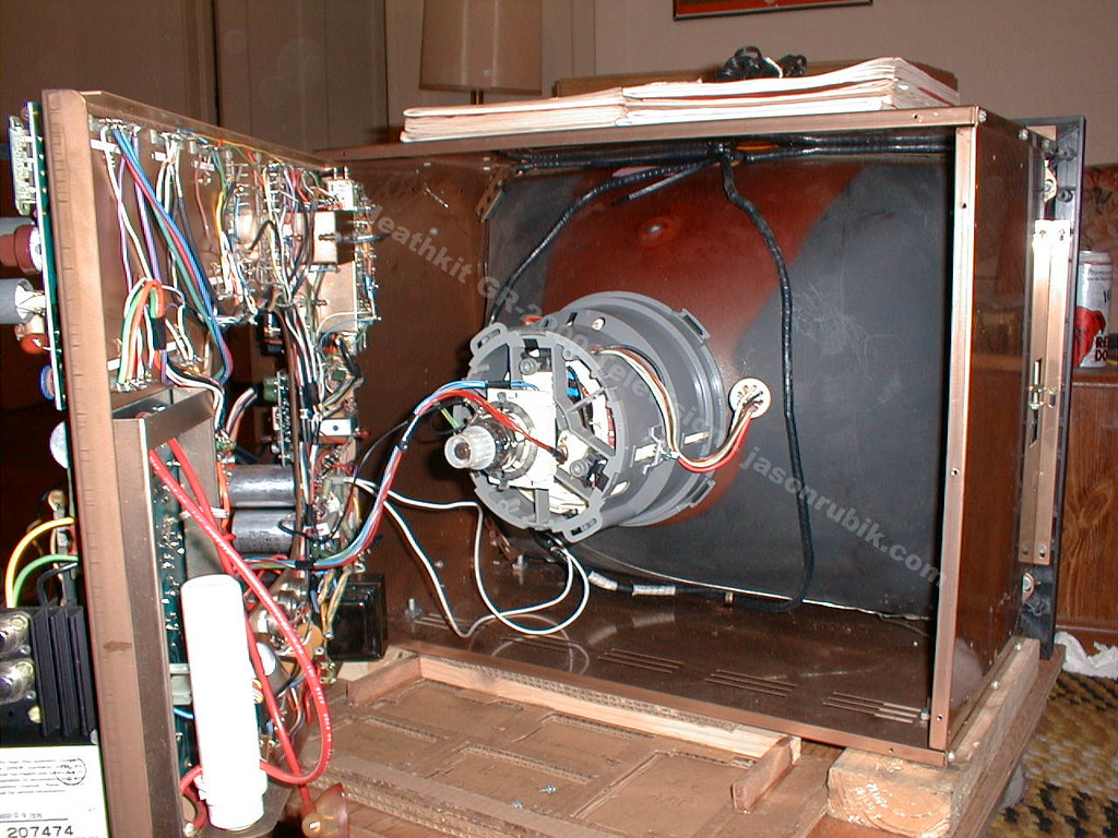
The GR-2000 used a 25-inch black (negative) matrix tube with fully illuminated phosphor dots and an etched faceplate to cut glare, warranted for two years — the same MTX-5 family of “ultra-rectangular” tubes Heath had introduced on the GR-371MX in 1972. The tube is enclosed in a steel “Magna-Shield” container that keeps stray magnetic fields off the mask and helps hold colour purity. Secondary sources give the tube type as 25VEDP22 (Radiomuseum); it is not named in the catalogue specification.
2.2 Changing channel without a knob
The tuning system is the heart of the set, and it is a piece of small-scale digital logic that would look at home in a 1974 instrument.
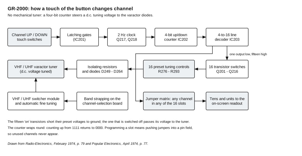
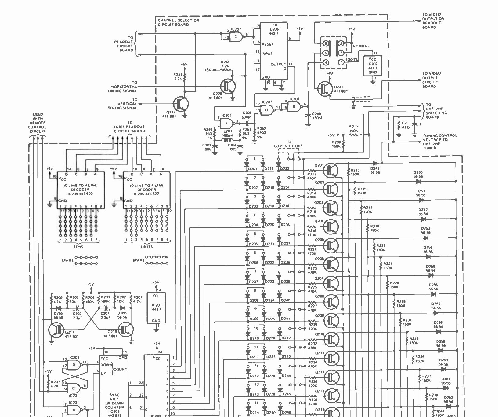
A two-hertz multivibrator built from Q217 and Q218 runs continuously. Touching the up or down switch on the front panel opens one of two latching gates formed from sections of IC201, and the pulses reach the corresponding input of IC202, a four-bit up/down counter. Each pulse advances the count by one; hold the switch down and the set steps through the channels at two per second. The counter wraps: counting up from 1111 the next pulse gives 0000, and counting down from 0000 gives 1111.
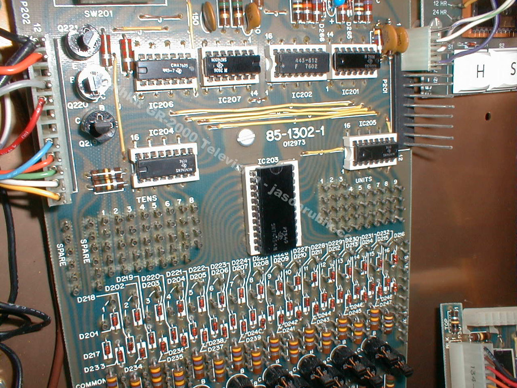
The counter’s four output lines drive IC203, a four-line to sixteen-line decoder. For any count exactly one of its sixteen outputs is low and the other fifteen are high. Each output drives a transistor switch, Q201 to Q216, with an associated diode, D249 to D264. The fifteen transistors whose lines are high are saturated and clamp their inputs to about 0.3 volt, shorting their preset tuning voltages to ground. The single transistor whose line is low is cut off, so the voltage set on its preset control — R276 to R293, sixteen small potentiometers on a board in the service drawer — passes through its isolating resistor and diode to the varactor tuners. R294 calibrates the string.
The result is a tuner that has been “set” once, by the owner, for the sixteen stations he can actually receive. Because the channel number attached to each slot is defined separately, by jumper wires pushed into a pin field, any channel can be put in any slot and the same channel can appear twice. Unused channels are simply not programmed, so a viewer stepping through never lands on snow.
2.3 Writing on the screen
Putting a number on a television screen in 1974 meant turning the electron beams on and off at the right instants as they scanned, and doing it in step with the set’s own sweep. There was no frame store and no video memory; the digits exist only as timing.
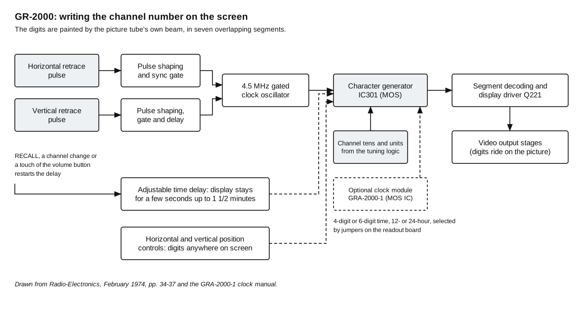
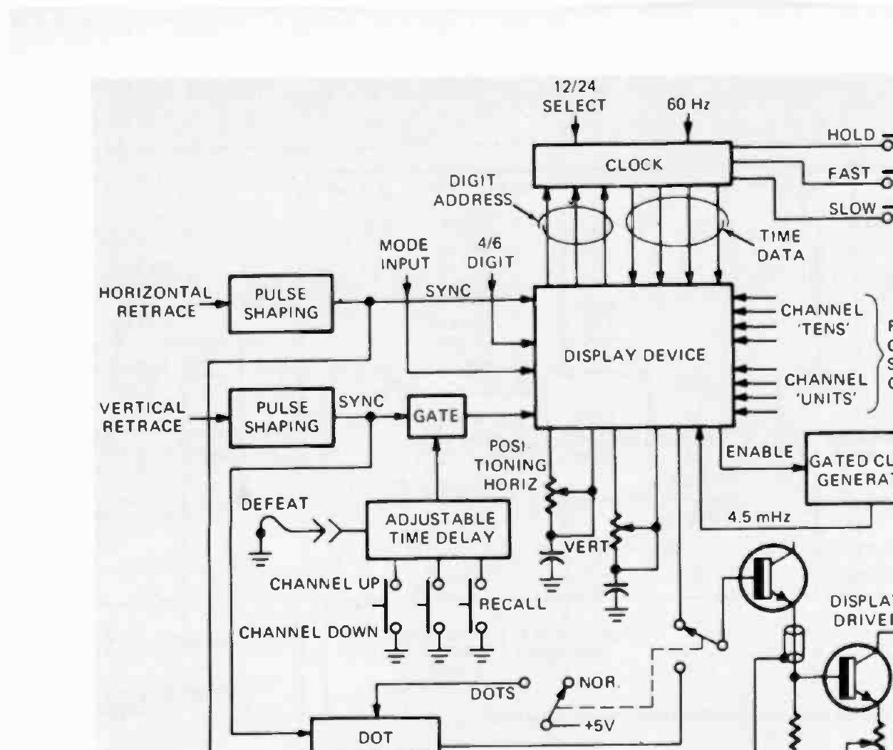
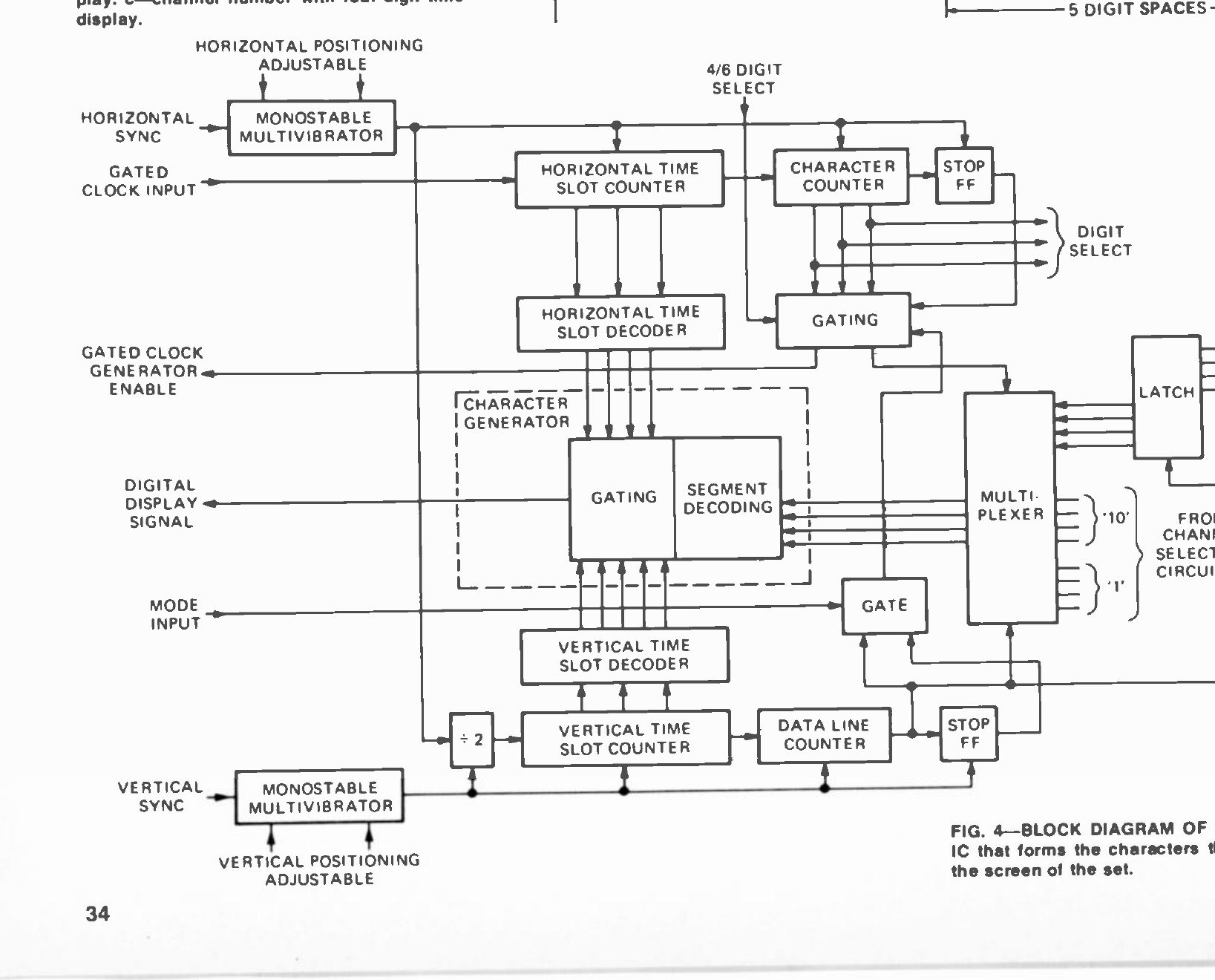
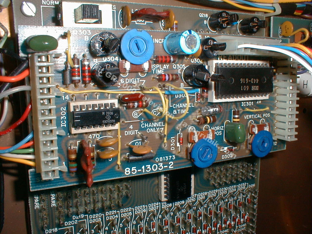
The display device is IC301, a custom MOS character generator. It takes horizontal and vertical retrace pulses as its time base: the horizontal pulses go straight in, while the vertical pulses pass through a gate and an adjustable time delay. A 4.5 MHz oscillator is gated on only when horizontal and vertical pulses are present together, so the character generator counts only inside the rectangle of screen where the digits belong.
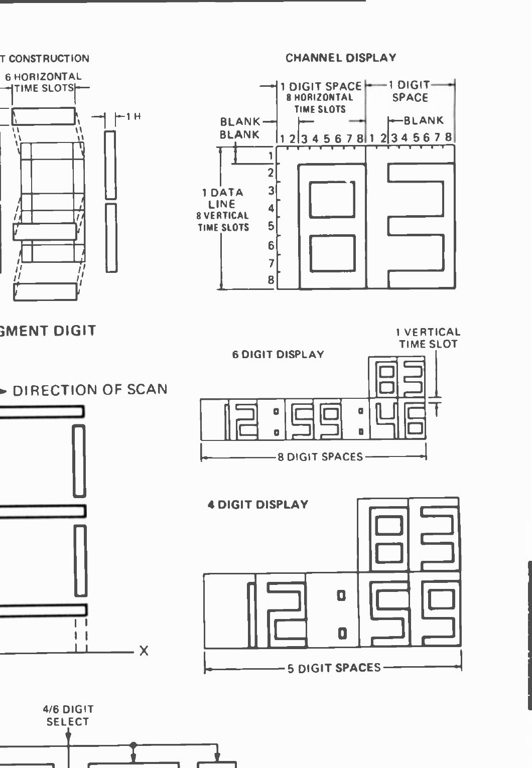
Each digit is drawn in seven segments, and Heath modified the shape of the standard seven-segment figure so that the segments overlap at their ends and the characters read as unbroken numerals rather than as assemblies of bars. Radio-Electronics set out the arithmetic of the character cell: six horizontal time slots and four or eight vertical time slots per digit, with blanking between digits. The set can produce a four-digit or a six-digit display, and either the channel number alone or the channel number with the time.
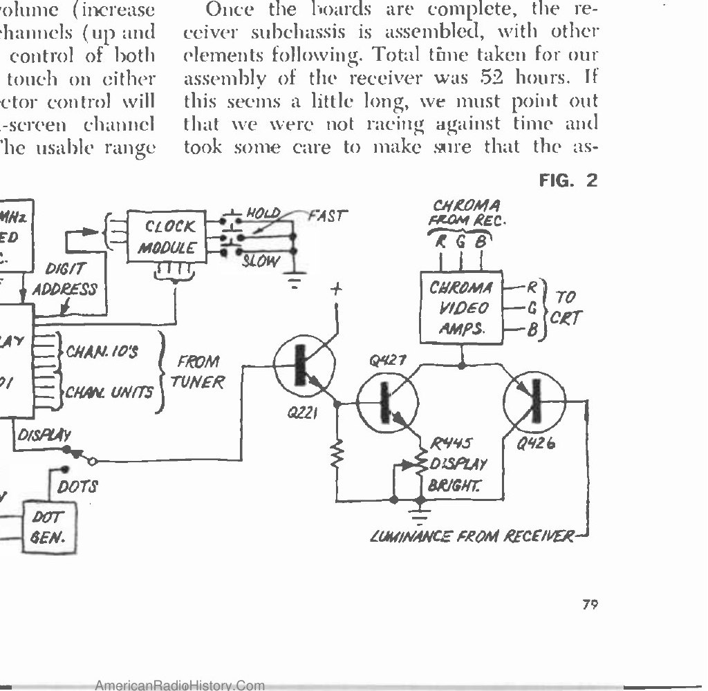
The output of the character generator passes through segment decoding to a display driver, Q221, and is inserted in parallel with the luminance signal at the video output stages: three chroma amplifiers carry the red, green and blue video, transistor Q426 inserts the luminance, and Q427 in parallel with it inserts the digits or the dot pattern. R445 sets how bright the display is relative to the picture.
Two controls on the readout board decide where the display appears and how long it stays. Horizontal and vertical positioning circuits let the digits be placed almost anywhere on the screen. The adjustable time delay holds the vertical gate open for a programmed period — a few seconds up to about a minute and a half — after which the gate closes, no vertical pulses reach IC301 and the display vanishes. Changing channel, touching RECALL or touching the volume button on the remote restarts the delay, and a jumper on the board makes the display permanent instead.
2.4 The clock module
The GRA-2000-1 accessory is, by the standards of the rest of the set, trivially simple — and that is the point of the architecture. All the hard work of putting characters on a screen is already done by the readout board, so the clock needs only to supply digits.
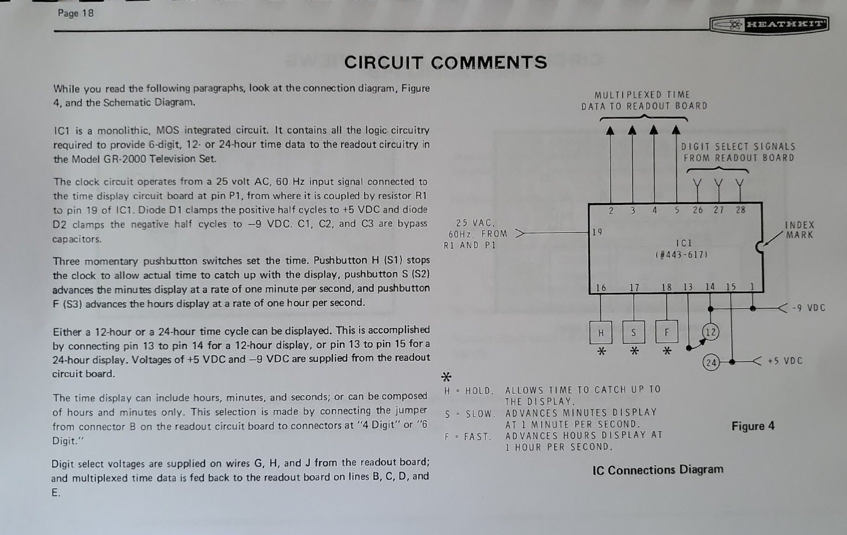
The module is a single small circuit board, Heath part 85-1305-1, carrying one monolithic MOS integrated circuit (Heath part 443-617), a resistor, three capacitors, two diodes and three pushbuttons. The IC contains all the logic needed to provide six digits of 12- or 24-hour time data to the readout circuitry. Its time base is the 60 Hz mains frequency: a 25-volt a.c. sample from the power supply arrives at pin P1 of the time-display board and is coupled through R1 to pin 19 of the IC, where D1 clamps the positive half-cycles to +5 V and D2 clamps the negative half-cycles to −9 V. The same ±5 V and −9 V rails, supplied from the readout board, power the logic.
Three momentary pushbuttons set the time and are labelled by function rather than by direction: H (hold) stops the clock so that real time can catch up with the display, S (slow) advances the minutes at one minute per second, and F (fast) advances the hours at one hour per second. Two jumpers do the configuration: pin 13 to pin 14 gives a 12-hour display and pin 13 to pin 15 a 24-hour display, while a jumper on the readout board between connector B and the “4 Digit” or “6 Digit” pins decides whether seconds are shown. Digit-select voltages come from the readout board on wires G, H and J, and the multiplexed time data goes back on lines B, C, D and E (GRA-2000-1 assembly and operation manual, pp. 16-19).
Two consequences follow. The clock keeps running when the set is switched off — it is fed from the standby supply — so the time is right when the picture returns. And because the time data is multiplexed into the same character generator that draws the channel number, the time inherits everything the channel display does: the same digit size, the same position controls, the same brightness setting and the same timeout.
2.5 The dot generator and the test meter
The GR-2000 carries its own convergence pattern generator: a single integrated circuit in which a gated oscillator, pulse shaping and a decade counter produce an array of small, well-defined white dots, switched in place of the channel and time display by the DOTS/NORMAL switch. Popular Electronics found the dots “rock-steady” and “small”, which matters because convergence is judged by how well three coloured dots coincide, and a soft or drifting dot hides the error. The magazine reported that the complete colour adjustments could be done in under an hour.
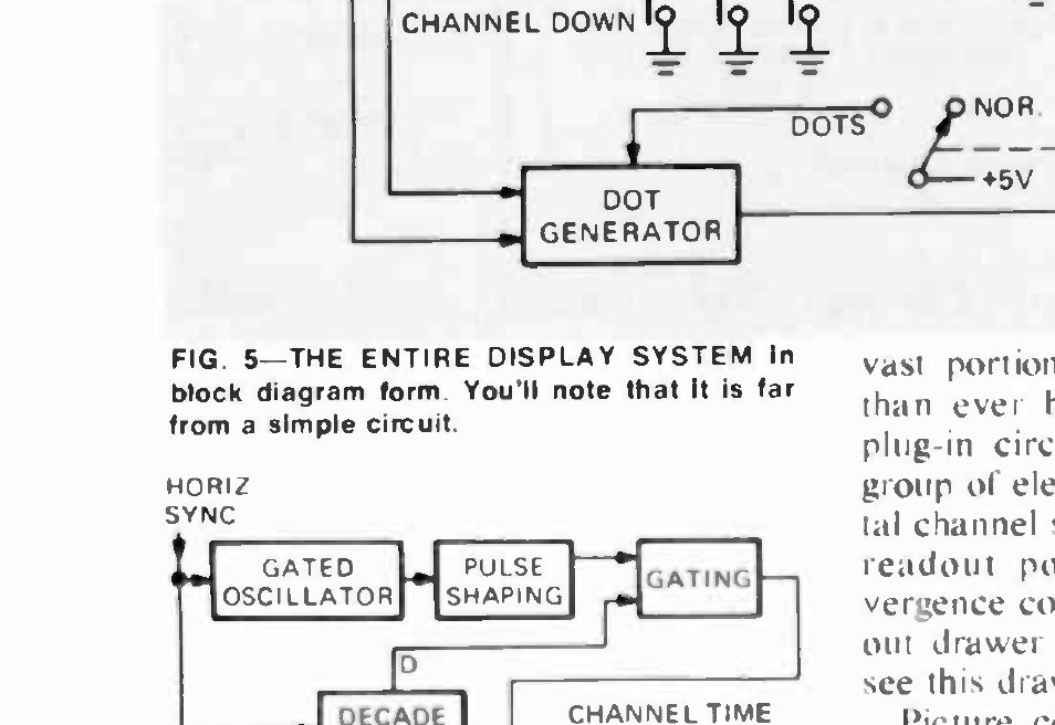
The set also contains a meter — Heath’s manuals call it the Troubleshooter — used first for resistance checks before the chassis is ever plugged in and then for the voltage readings that verify each supply rail. It lives in the chassis and is part of the product, not an accessory. Together with the dot generator, the purity and convergence adjustments and the slide-out service drawer, it is what Heath meant by its standing claim that because the owner built the set, the owner could service it.
2.6 The remote control
The GRA-2000-6 option is a small system in its own right. The hand-held transmitter has four rocker switches producing eight ultrasonic commands — on, off, volume up and down, channel up and down, and tint and colour intensity in both directions — from a single transistor running off a 9-volt battery, with a useful range of about twenty feet. The receiver, mounted inside the chassis and listening through a microphone concealed in the front panel, uses twenty-eight transistors, twelve integrated circuits and eight diodes. One section detects which command has arrived and a second remembers the resulting state.
The analogue functions are handled digitally: colour and tint each have an eight-bit up/down counter with a latching gate and a digital-to-analogue converter, and volume has a four-bit counter, its own converter and the circuits that work the a.c. power relay. In the set, these elements parallel the ones already on the chassis, which is why touching the volume button also recalls the on-screen display (Popular Electronics, April 1974, p. 80).
2.7 What it added up to
Read as a whole, the GR-2000 is an argument that digital logic belonged in a television for reasons other than novelty. The counter and decoder removed the turret tuner, the commonest mechanical failure in a 1970s set. The fixed filter removed the alignment. The character generator gave the viewer information the set already had but could not previously show. And the built-in dot generator and meter turned a job that needed a service call into an afternoon with a screwdriver. Radio-TV Repair drew the conclusion in March 1974 in one line: “the GR-2000 is the way all TV sets will have to be made in the future.”
Sources
- Larry Steckler, “Heathkit’s new digital color TV”, Radio-Electronics, February 1974, pp. 33-37 and 78-80.
- “Heathkit Model GR-2000 Digital Color TV Receiver with optional remote control and clock”, Popular Electronics, April 1974, pp. 77-80.
- Heathkit GRA-2000-1 TV Clock Accessory, assembly and operation manual, Internet Archive.
- Heathkit GR-2001 Color Television, Book Three: Adjustment and Operation, 595-1865-06 (1976), Internet Archive.
- Heathkit catalogue 800/95, March 1974 and Christmas 1975 catalogue (specifications and feature descriptions).
- “Heathkit GR-2000 Solid State Color TV”, VideoKarma forum thread.
- GR-2000 entry, Radiomuseum (picture tube type; secondary).
Comments (0)