GR-2000 Color Television · Volume 3
Building the Kit
A GR-2000 arrived as cartons of parts, a picture tube in its own crate and a set of manuals thick enough to stand up on a shelf. Nothing about it was quick. Heath had advertised its 1965 tube-type colour sets as assembling “in just 25 hours”; the magazine that timed a GR-2000 build in 1974 stopped the clock at fifty-two, and noted that it had not been hurrying. Set against that, the person who finished one owned a television nobody could buy, understood its insides, and had the instruments to keep it right built into the cabinet.
This volume describes the kit as it came out of the box, the structure of the manual, the order of work, the steps that caused trouble and the time it took. The alignment and convergence that follow assembly are the subject of the next volume.
3.1 What was in the cartons
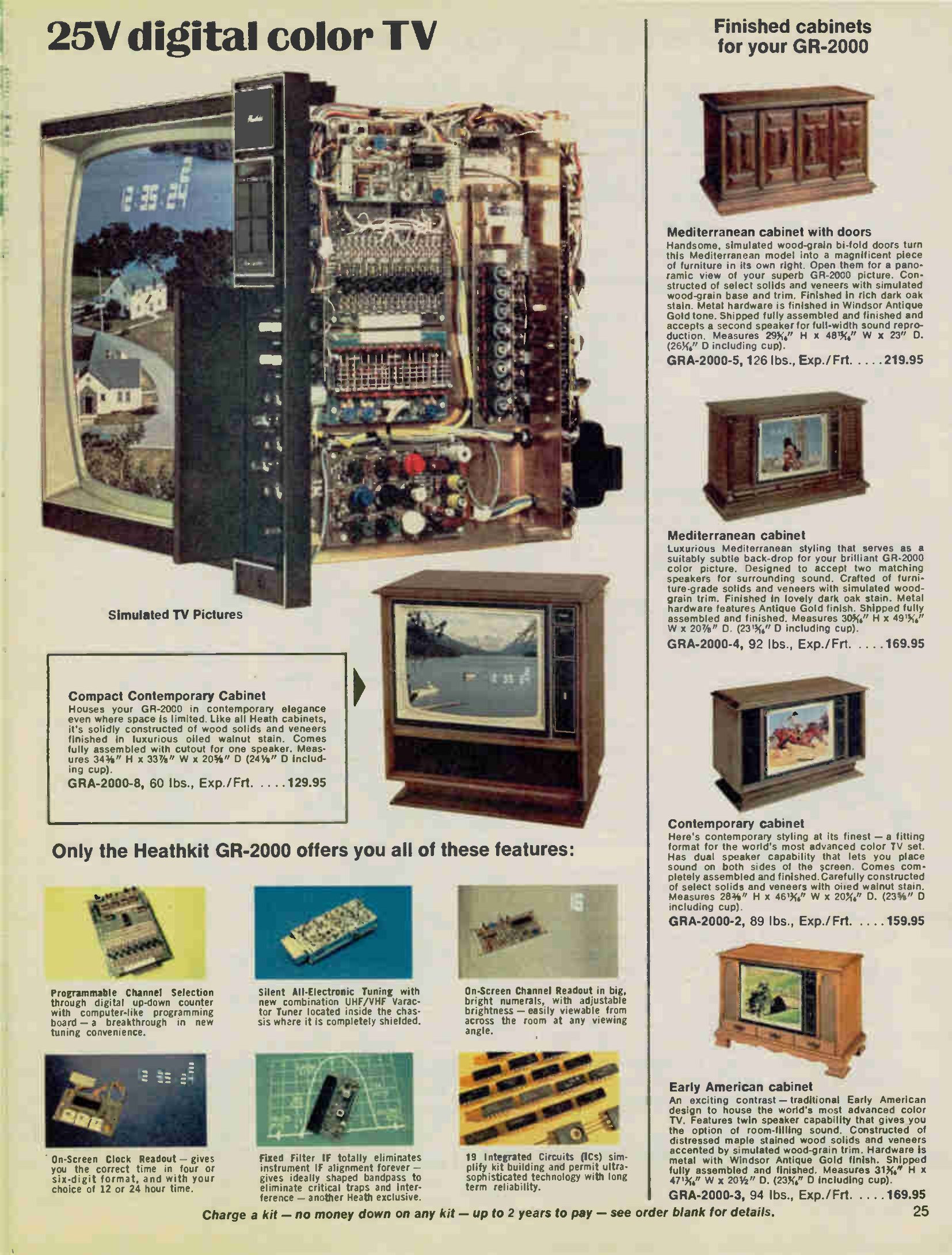
The kit as sold comprised the chassis parts, the picture tube and one speaker, shipping at 147 pounds by motor freight. The cabinet, the remote control, the clock and a second speaker were separate orders.
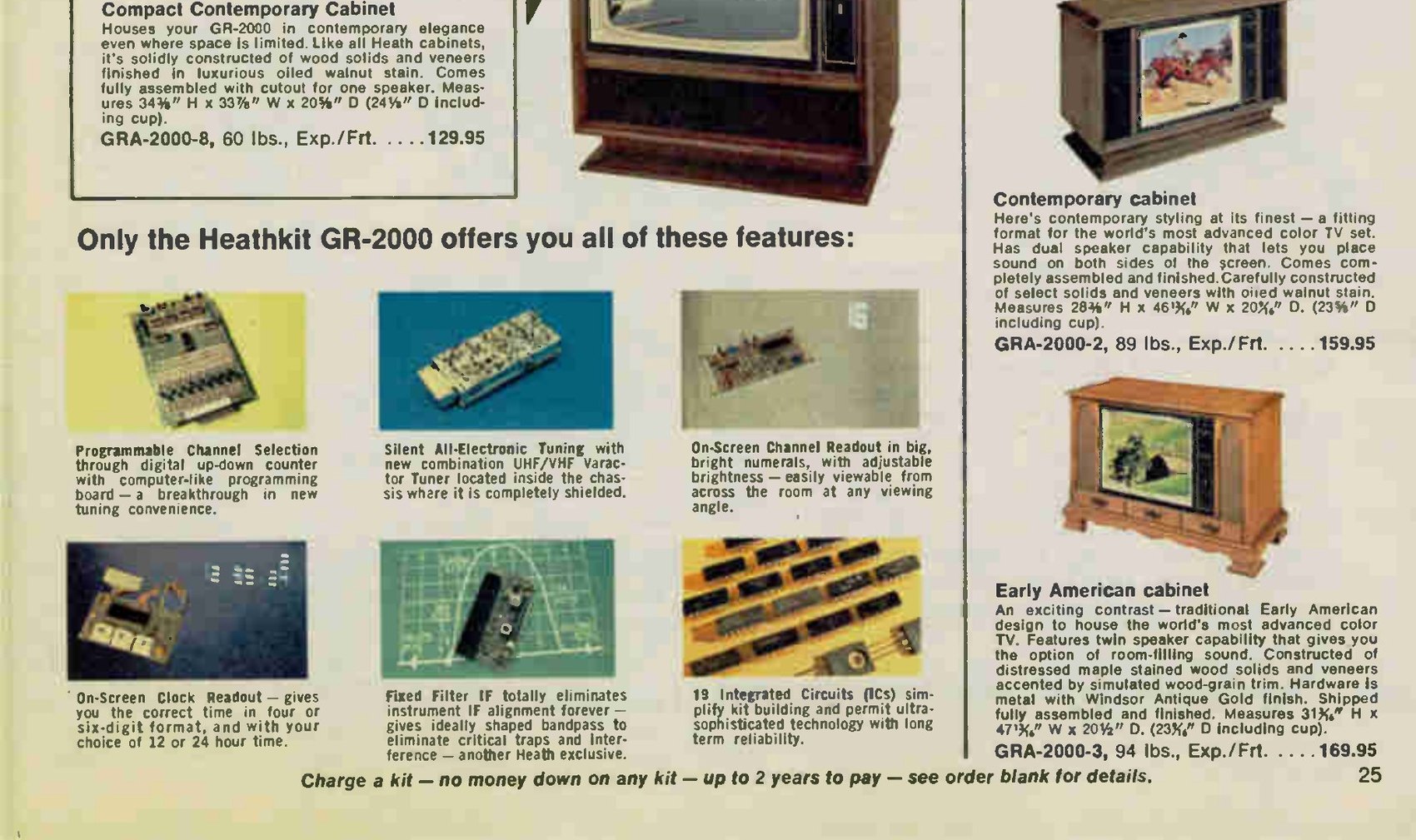
Inside, the striking thing was how much of the work had already been done. The tuners came built and aligned. The intermediate-frequency filter was sealed in a double-shielded can and never needed adjustment. There were twelve factory-fabricated interconnecting cables, so the harness lacing that had eaten evenings on earlier kits was largely gone. Every semiconductor had its own socket — seventy-one transistors and nineteen integrated circuits — so nothing was soldered that might later have to be unsoldered. And the electronics were divided across twenty glass-epoxy circuit boards, each one packed with its own components in its own sub-pack.
That packing method was deliberate, and Heath had described the logic of it to its parent company two years earlier: the parts for a colour television came in sub-packs so that a builder who reached the last step of a board with a part left over knew immediately that he had made an error, and knew which board to look at (Schlumberger annual report, 1972). The same report records what had happened to Heath manuals by then — up to 350 pages and 700 illustrations, and for the colour television, four volumes.
3.2 The manual
Heath’s manuals are described in general in the company history dive; what matters here is how the GR-2000’s set was divided. Dealer and collector listings of complete sets describe five numbered books — Book One, assembly; Book Two, chassis; Book Three, adjustments and operation; Book Four, “in case of difficulty”; Book Five, alignment and data — together with a separate GR-2000 Subchassis and Picture Tube assembly manual, all dated 1973. No free scan of the GR-2000 books has been found, so the division above rests on sale listings rather than on a copy examined for this dive.
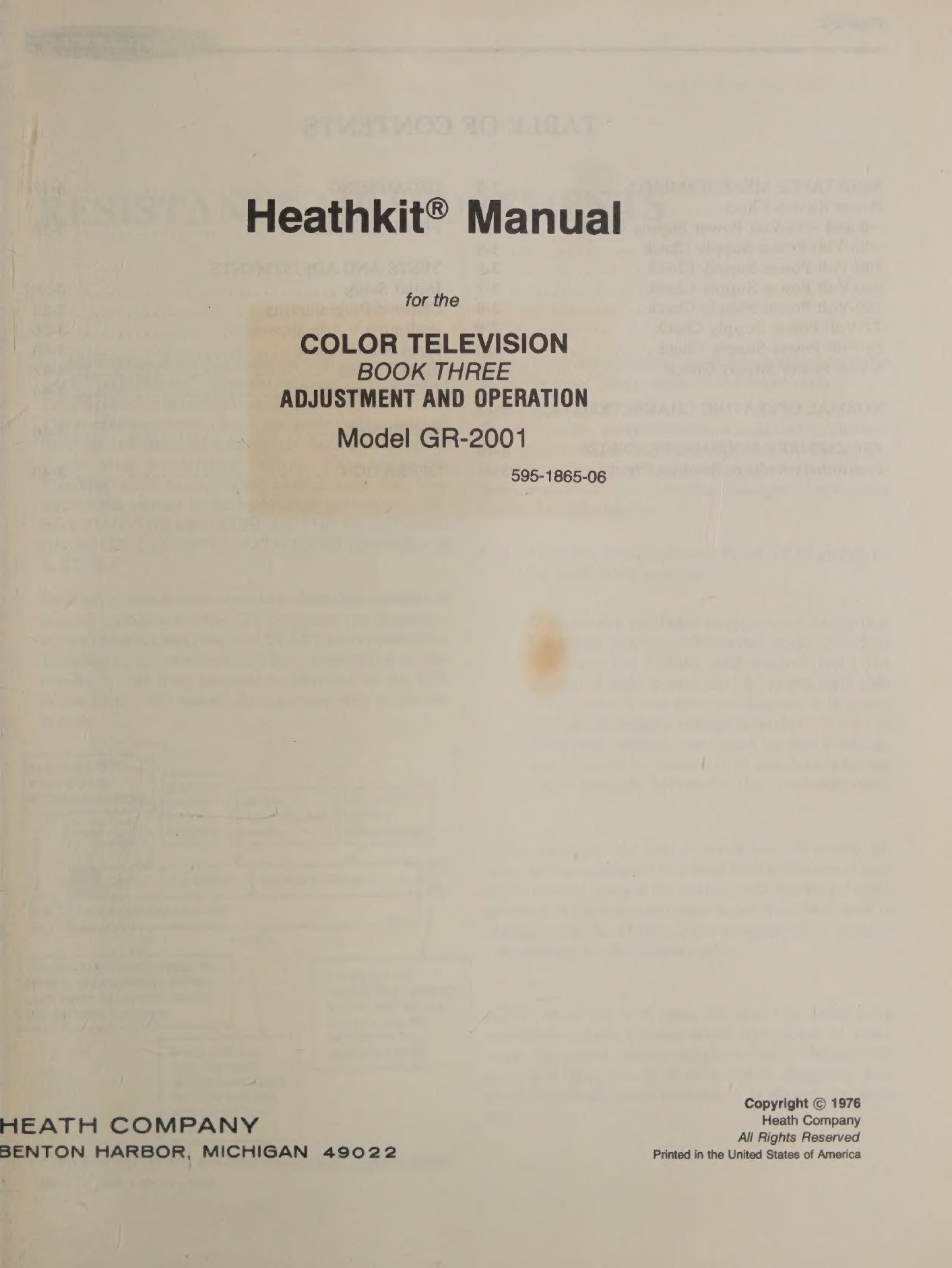
The structure can, however, be read directly from the surviving Book Three for the GR-2001, the closely related successor, which is online in full. Its table of contents runs: resistance measurements, normal operating characteristics, preliminary voltage readings, degaussing, final assembly, then tests and adjustments — initial set-up, channel programming, preliminary adjustments, final adjustments, final tuning, a.f.t. alignment — then antennas and operation (GR-2001 Book Three, 595-1865-06). The cross-references in it point to “Book 4, Page 4-46” for high-voltage troubleshooting and to an Illustration Booklet for the fold-out pictorials, which shows how the set of books worked together in practice: the step-by-step text in one hand, the pictorial in the other.
3.3 The order of work
Both contemporary accounts describe the same sequence, and it is the sequence the modular design dictates.
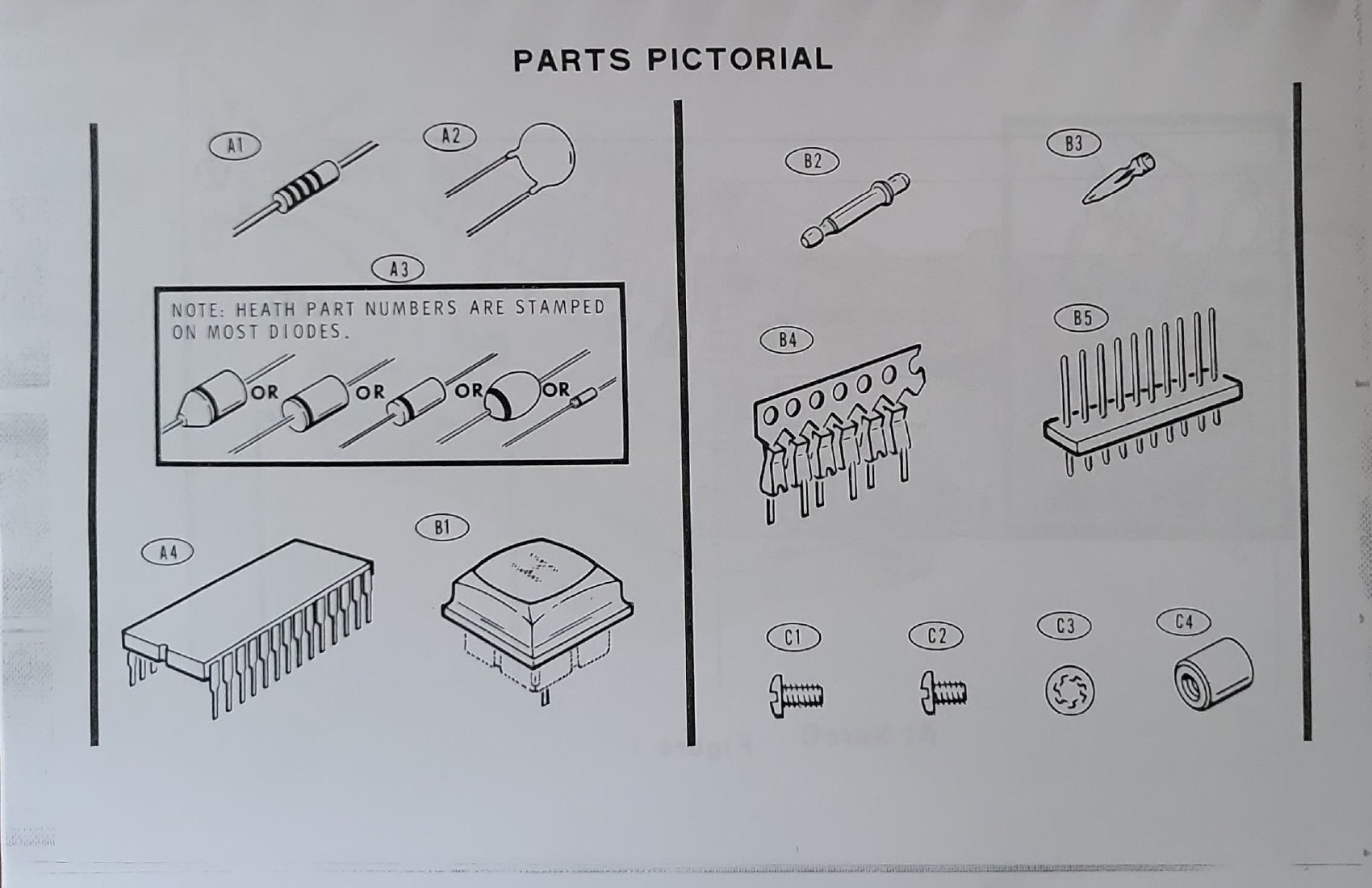
First, the twenty circuit boards. Each board is built from its own bag of parts, following the pictorial for that board. Popular Electronics found the work straightforward: assembling the boards was easy if the manual was followed, with each step clearly identified and enough illustrations to satisfy “even the most fastidious assembler”. Because the semiconductors are socketed, board assembly is resistors, capacitors, sockets and a handful of small components, with the delicate devices inserted afterwards.
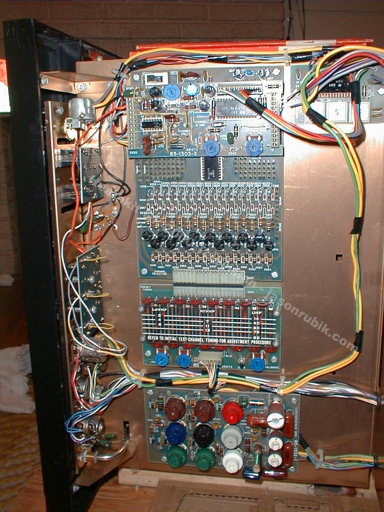
Then the sub-chassis. The mechanical heart of the set is assembled next: the frame, the tuners, the power supply, the slide-out service drawer with the preset tuning controls, the readout board, the convergence board and, if fitted, the clock module.
Then the picture tube and its shield. The 25-inch tube goes into the steel Magna-Shield container with the circuit elements mounted on the rear apron, the yoke and convergence assembly go on the neck, and the whole assembly is married to the chassis. This is the point in a colour television kit at which a builder needs a second pair of hands and a clear bench: the tube is heavy, its neck is fragile, and the anode connection stores a charge.
Then the wiring. The twelve pre-made cables and the harnesses go in, boards are plugged into their connectors, and the aerial terminals, speaker and controls are connected.
Then the checks before power. The manual’s resistance measurements come next, made with the built-in Troubleshooter meter and with the set unplugged — a chain of charts that walk the builder through every supply rail and its load so that a wiring error is found before it can destroy a component.
3.4 How long it took
Popular Electronics reported the only independently timed figure that has been found: the magazine’s own build took 52 hours, and the reviewers noted that they had not been racing the clock but working carefully so that the finished set would work first time (Popular Electronics, April 1974, p. 80).
Fifty-two hours is a multi-week project at the pace of a weekday evening plus weekends, and that is before the convergence session. The remote control and the clock add their own assemblies: the clock is genuinely an evening’s work, being one small board, while the remote control contains twelve integrated circuits and twenty-eight transistors of its own. Heath’s own line was that the clock could be built “in just a couple hours’ time”.
3.5 Tools and space
The kit needed no test instruments — that was the design premise — but it needed the ordinary bench kit and, more than anything, room. A 25-watt to 40-watt soldering iron and fine solder for the boards; the usual nut drivers, pliers and cutters; a solder sucker or braid for mistakes; a clear table big enough for a chassis that finishes at 112 pounds; and somewhere the half-built set could sit undisturbed for a month. The service drawer, the convergence board and the preset controls all have to be reachable during set-up, so the chassis is worked on out of its cabinet and only installed afterwards.
The one instrument not in the box, for anyone building the set today, is a means of feeding it a signal: an off-air aerial in a good signal area in 1974, and for a modern set-up a digital-to-analogue converter box or a pattern generator with an r.f. output on a VHF channel.
3.6 The difficult steps
Four places in the build reward care, judging by the manuals and by what restorers have reported since.
The picture tube and its high-voltage connection. The manual’s instruction is to discharge the tube before connecting or disconnecting the anode connector, and to work near high voltage with one hand behind the back. The charge stored between the inner and outer conductive coatings of the tube is real whether or not the set has been switched on recently.
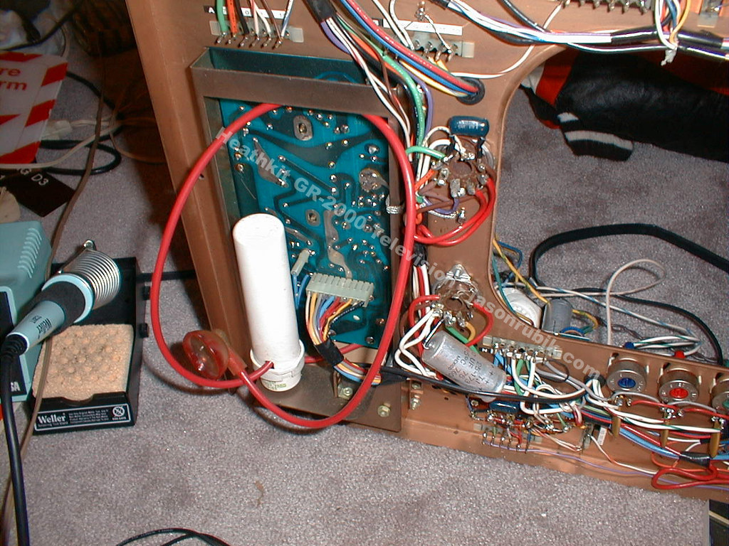
Board identification and orientation. With twenty boards and multi-way connectors, a board can be put back in the wrong place or the wrong way round. A restorer on VideoKarma describes exactly that error costing him the vertical deflection after a recapping session (VideoKarma, “Heathkit GR-2000 Solid State Color TV”).
The integrated circuits and their connectors. The GR-2000’s ICs are not soldered in but sit on strips of individual connectors. The clock manual’s instructions give the flavour of the work: cut a strip of fourteen connectors, check that the staggered pins line up with the two rows of holes, keep the connecting band outward, and do not remove the MOS clock IC from its conductive foam until the step that calls for it (GRA-2000-1 manual, pp. 3-5). Static precautions in 1974 amounted to leaving the device in its foam until the last moment.
Channel programming. This is not soldering at all but a logical exercise with a field of pins, and it is the step most likely to be got wrong twice. It is covered in the next volume.
3.7 What builders said
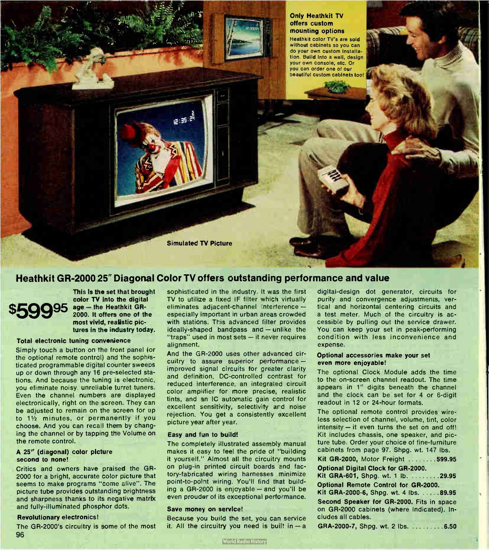
Contemporary testimony about the GR-2000 specifically is thin, because Heath’s published owner letters belong mostly to the tube-set era. The 1977 catalogue’s own summary is a fair statement of the design intent: the illustrated manual let the owner “feel the pride of ‘building it yourself’”, with almost all the circuitry on plug-in boards and factory-made harnesses in place of point-to-point wiring (Fall 1977 catalogue, No. 817, p. 96).
The verdict that carried most weight at the time came from the trade. Radio-TV Repair — a magazine for people who fixed televisions for a living — wrote in March 1974 that earlier attempts at modular colour television had put many complex circuits on each module, leaving them too hard for an owner to troubleshoot, whereas the GR-2000 broke nearly every function down to its own small plug-in assembly — so that building and adjusting the set taught the owner what was in it, and a fault meant pulling one board and checking it (quoted in the March 1974 catalogue, p. 3).
Modern builds are rare but they happen: the set still appears on the vintage-television forums, and at least one full build has been documented on video (“Building a 1976 Heathkit GR-2000 25” Color TV”, YouTube). Unbuilt kits surface occasionally, which is how a 2020s builder can have the same experience as a 1974 one — with the difference that an unbuilt kit’s electrolytic capacitors are now fifty years old before they have ever been powered.
Sources
- “Heathkit Model GR-2000 Digital Color TV Receiver”, Popular Electronics, April 1974, pp. 77-80.
- Larry Steckler, “Heathkit’s new digital color TV”, Radio-Electronics, February 1974, pp. 33-37, 78-80.
- Heathkit GR-2001 Color Television, Book Three: Adjustment and Operation, 595-1865-06 (1976), Internet Archive.
- Heathkit GRA-2000-1 TV Clock Accessory manual, Internet Archive.
- Heathkit catalogue 800/95, March 1974; Christmas 1975; Fall 1977, No. 817.
- Schlumberger Limited annual report, 1972 (manual volumes, parts sub-packs).
- “Heathkit GR-2000 Solid State Color TV”, VideoKarma forum thread.
Comments (0)