SB-102 Transceiver · Volume 4
Alignment and Use
The SB-102’s alignment is shorter than the HW-101’s in one important way: there is no VFO to align. The LMO arrives pre-aligned, linearised and sealed, and the only adjustment the builder is allowed to make is the sideband-shift screw on its top. Everything else is conventional for a Heath SB transceiver. The receiver IF and heterodyne oscillator are aligned against the built-in 100 kHz calibrator; the driver and preselector coils are peaked in a fixed order; the finals are neutralised and the carrier nulled into a dummy load; and the dial is set against WWV. This volume outlines that sequence and the reasons for it, then covers the controls and how the rig is operated. It is a guide to the manual, not a substitute for it.
4.1 Before any of it: the voltages inside
The initial-test page puts it in capitals: “LETHAL VOLTAGES ARE PRESENT BOTH ABOVE AND BELOW THE CHASSIS.” The finals’ plate supply is 800 to 900 volts from the power supply, the B+ line is 300 volts, and alignment is done with the cabinet off and the rig powered. The manual’s instructions are to earth the chassis and all test equipment to a good ground, to use well-insulated tools for adjustments, and never to remove a tube or pilot lamp with power applied. The last of those is peculiar to this family of rigs. In mobile use the 12-volt heaters are wired series-parallel, so pulling one tube with power on can put excess current through the others and destroy them.
4.2 The equipment
The manual’s list is short.
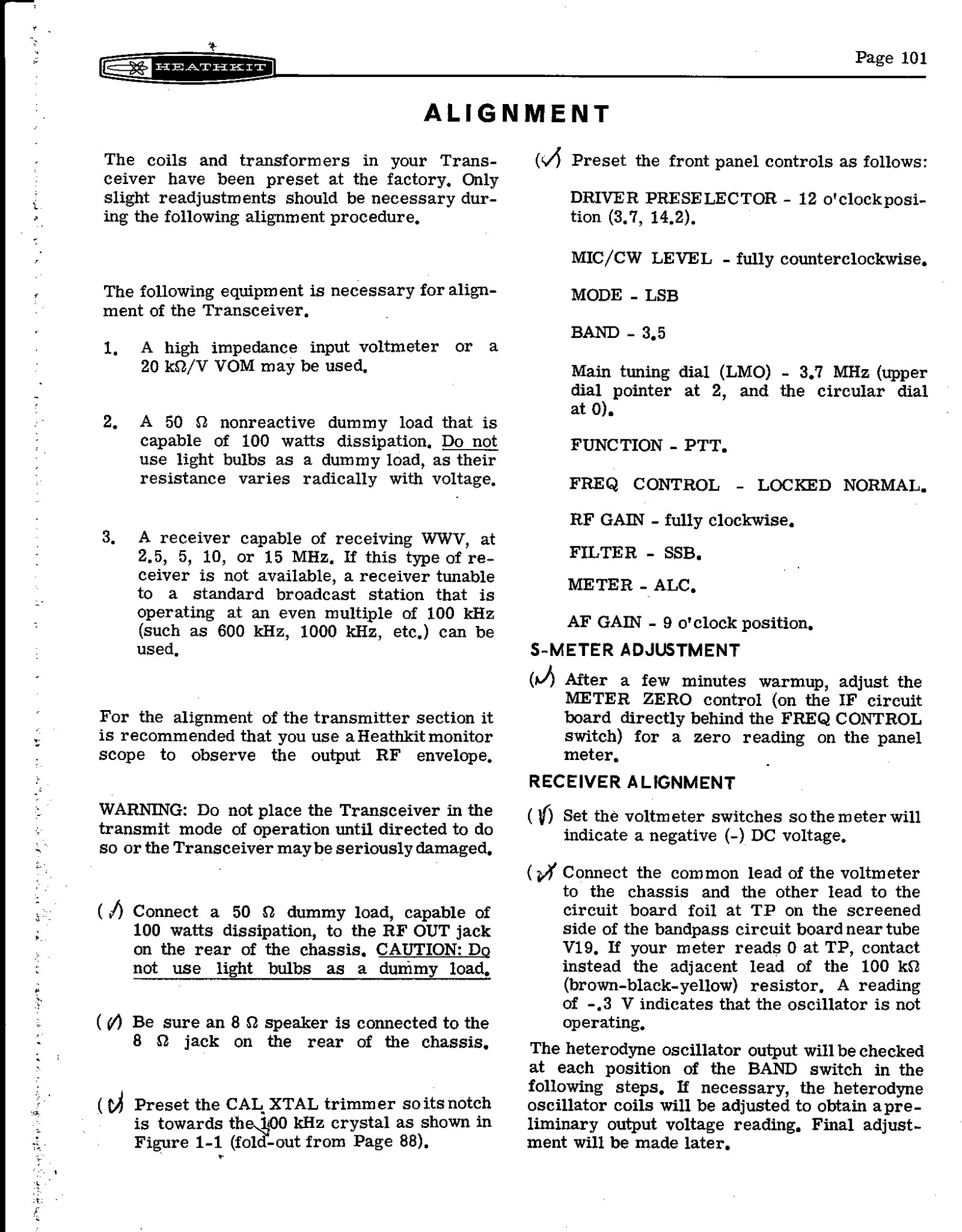
- A voltmeter. A high-impedance voltmeter, or a 20,000 Ω/V VOM.
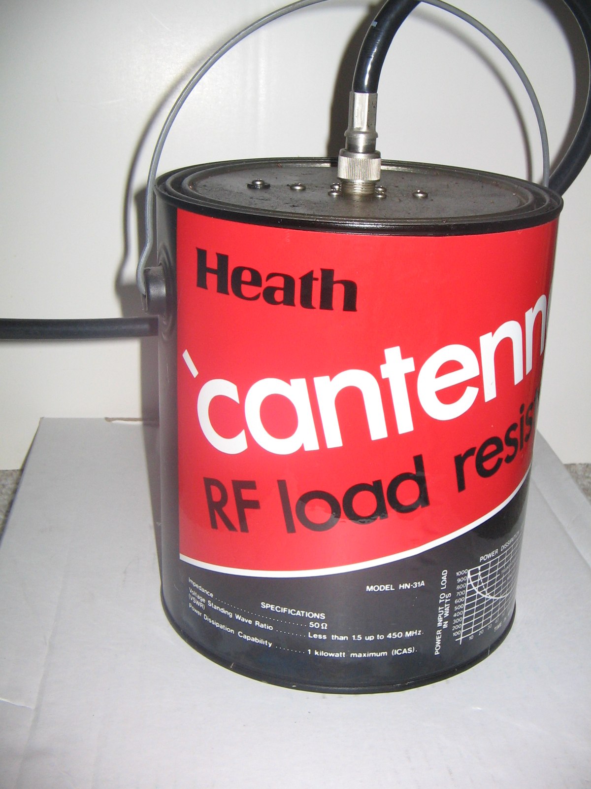
- A dummy load. It must be a non-reactive 50 Ω load rated for 100 W. The manual adds, twice, not to use light bulbs, “as their resistance varies radically with voltage”.
- A time signal. A receiver that can hear WWV at 2.5, 5, 10 or 15 MHz, or failing that a broadcast station on a multiple of 100 kHz, for the calibrator.
- A monitor scope (recommended). For the transmitter, the manual recommends a Heathkit monitor scope to watch the RF envelope. The SB-610 was built for this job, and Heath lists one among the equipment it used to prepare the SB-102’s own specifications.
4.3 Receiver alignment
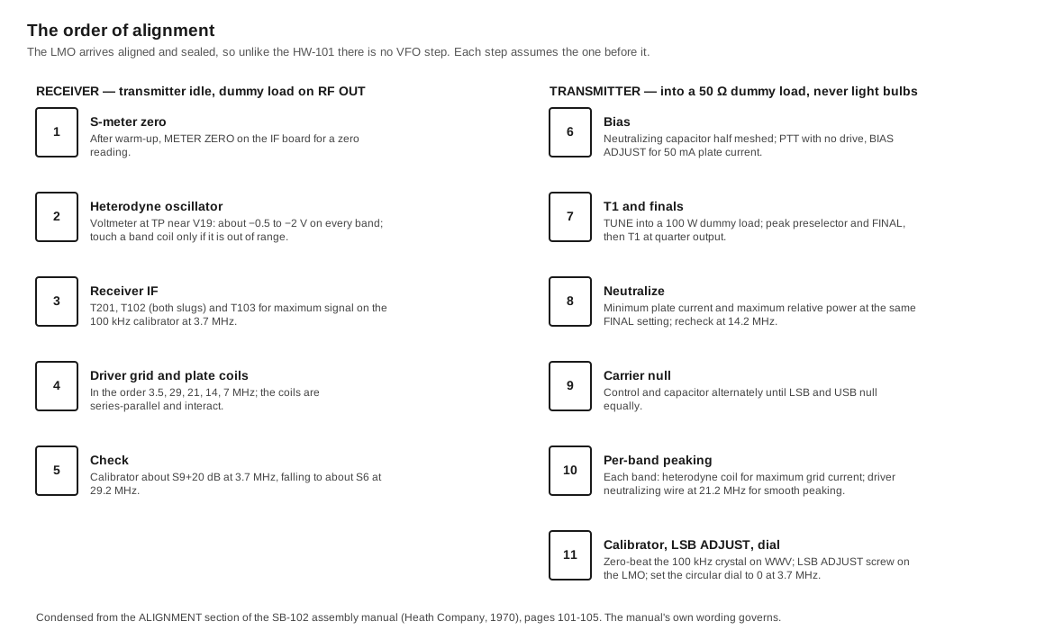
The coils and transformers are preset at the factory, and the manual expects “only slight readjustments”. The sequence, drawn out in the diagram below, runs as follows.
- S-meter zero. After a few minutes’ warm-up, the METER ZERO control, on the IF board behind the FREQ CONTROL switch, is set for zero with no signal.
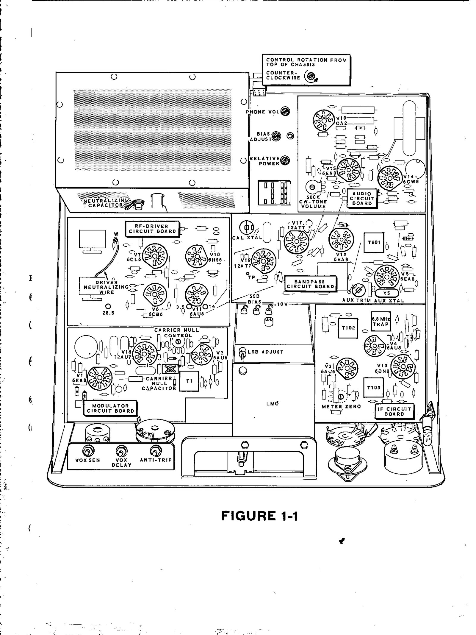
- Heterodyne oscillator. A voltmeter at the test point near V19 on the bandpass board reads the oscillator’s grid bias. It should be about −0.5 to −2 volts on every band. A reading of −0.3 V means the oscillator is not running. Coils are adjusted only for a band that falls outside that range. The manual adds a useful hint: on one side of the peak the voltage changes quickly and on the other slowly, and the coil should be set on the slow side.
- IF transformers. With the calibrator on and the dial at 3.7 MHz, T201, both slugs of T102, and T103 are peaked for maximum signal, and the manual warns that T201 and T103 should never need more than two turns. From this point the S-meter is the output indicator and the calibrator is the signal source.
- Driver grid and plate coils. These are peaked band by band in a fixed order: 3.5, then 29, 21, 14 and finally 7 MHz. The coils are in series-parallel, so each band’s inductance includes the coils of the bands before it, and working out of order undoes earlier adjustments. The DRIVER PRESELECTOR is set to the band’s marked position and the calibrator is identified by rocking the FUNCTION switch between VOX and CAL.
A properly aligned receiver, the manual says, will show the calibrator at about S9 plus 20 dB at 3700 kHz, falling to about S6 at 29.2 MHz.
4.4 Transmitter alignment
The transmitter is aligned into the dummy load with the coil cover in place, since the manual notes it must be fitted for transmitter operation.
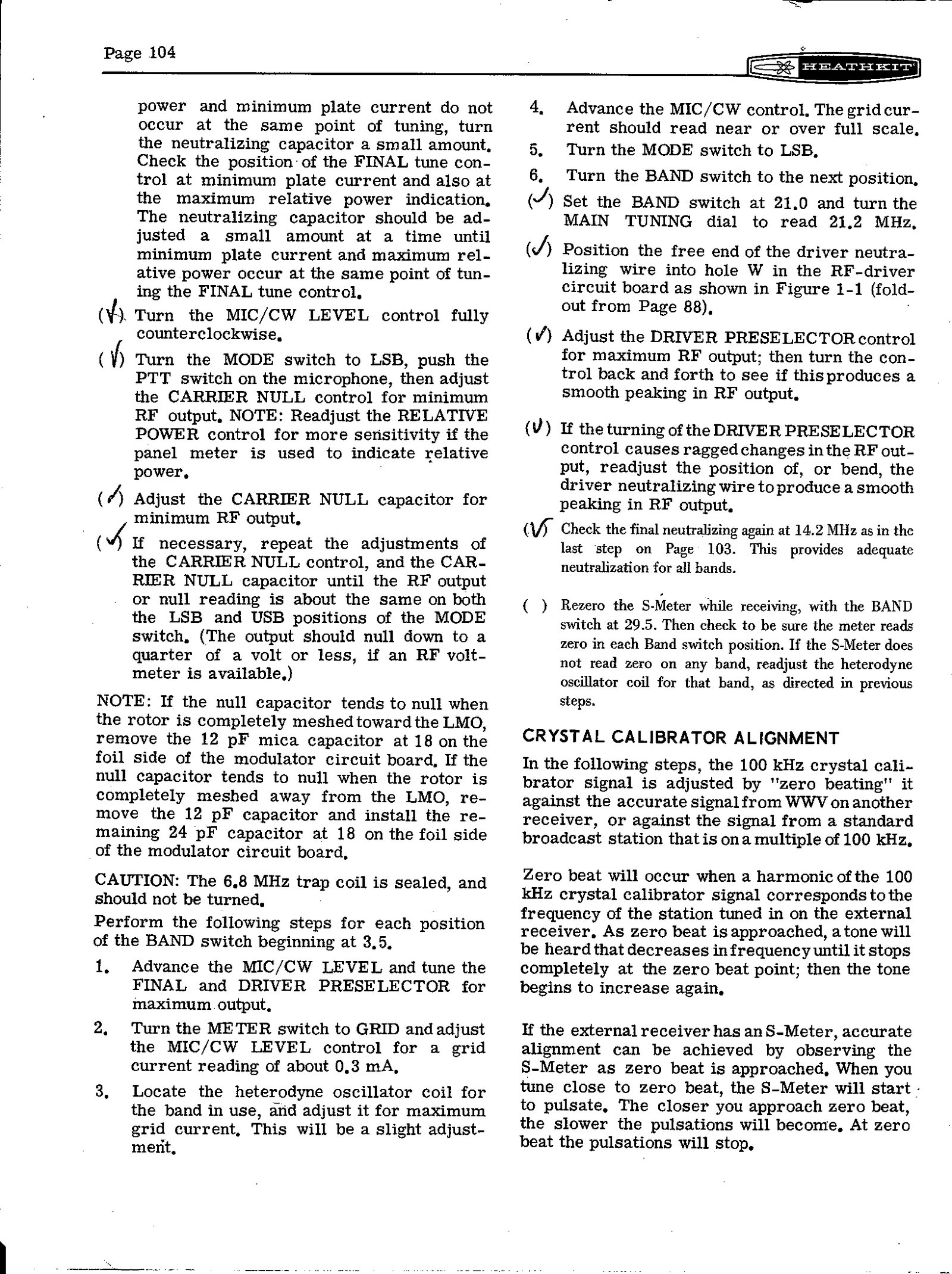
- Bias. The neutralizing capacitor on the RF cage is preset to half mesh. With the rig in LSB and PTT held, BIAS ADJUST is set for 50 mA of plate current. If the meter reads over 100 mA, the manual warns, the button should not be held more than a few seconds at a time until the bias is right.
- First peaking. In TUNE, with the MIC/CW LEVEL control advanced a little, the DRIVER PRESELECTOR and FINAL tuning are peaked, and balanced-modulator transformer T1 is peaked at about quarter output. It should not need more than one turn.
- Neutralising the finals. The METER switch alternates between PLATE and REL PWR. The FINAL tuning should give minimum plate current and maximum relative power at the same setting. If it does not, the neutralizing capacitor is moved a little at a time until the two coincide. This is done at 3.7 MHz and rechecked at 14.2 MHz, which the manual says “provides adequate neutralization for all bands”. Service bulletin SB-102-8 of May 1974 later gave an alternative method using a VTVM with an RF probe, with the finals’ plate and screen supplies disconnected for safety.
- Carrier null. In LSB with PTT and no speech, the CARRIER NULL control and CARRIER NULL capacitor are adjusted alternately for minimum output. The null should be about equal on LSB and USB, “a quarter of a volt or less” on an RF voltmeter. If the capacitor will only null fully meshed toward or away from the LMO, the manual has the builder swap a 12 pF or 24 pF capacitor at point 18 on the modulator board. Service bulletin SB-102-18 of July 1978 returned to the same problem, moving the 12 pF capacitor to the other section of the null trimmer.
- Band by band. On each band, with a little grid current showing, the heterodyne oscillator coil for that band is peaked for maximum grid current.
- Driver neutralisation. At 21.2 MHz, the free end of the driver neutralizing wire goes into hole W on the RF-driver board. It is then repositioned or bent until turning the DRIVER PRESELECTOR gives a smooth peak rather than a ragged one.
- S-meter recheck. With the band switch at 29.5 the S-meter is re-zeroed, then checked for zero on every band; a band that does not zero needs its heterodyne coil touched up.
The 6.8 MHz trap coil is sealed, and the manual says it “should not be turned”.
4.5 Calibrator, sideband shift and dial
The last three adjustments set the frequency readout.
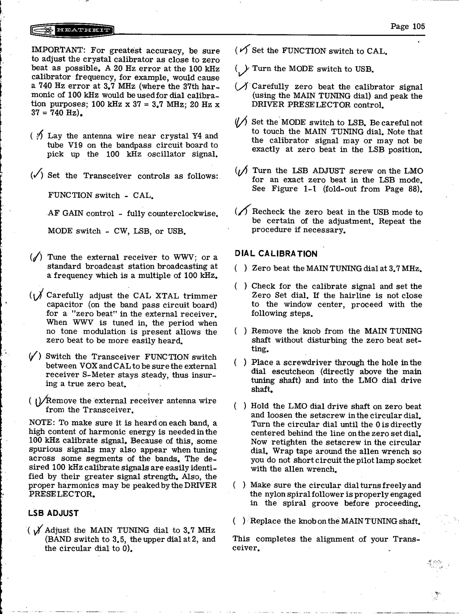
The crystal calibrator is zero-beaten against WWV, or a broadcast station on a multiple of 100 kHz, heard on a separate receiver with its antenna lead laid near crystal Y4 and V19 on the bandpass board. The manual explains why this has to be exact: “A 20 Hz error at the 100 kHz calibrator frequency… would cause a 740 Hz error at 3.7 MHz”, because the 37th harmonic is in use there. It suggests watching the other receiver’s S-meter, whose pulsing slows to a stop at zero beat.
The LSB ADJUST screw on the LMO is the one LMO adjustment the builder makes. With the calibrator zero-beaten in USB at 3.7 MHz, the MODE switch is moved to LSB without touching the dial, and the screw is turned for zero beat again. The dial now reads the same on both sidebands.
Dial calibration is mechanical. With the dial zero-beaten at 3.7 MHz, the builder removes the tuning knob, passes an Allen wrench through the small hole in the escutcheon to hold the LMO shaft, loosens the circular dial’s setscrew, and turns the dial until 0 sits under the hairline of the zero-set dial. The manual’s note to wrap tape round the wrench “so you do not short circuit the pilot lamp socket” is a small reminder that the dial lamp is live.
The specification promises visual dial accuracy within 200 Hz and electrical accuracy “within 400 Hz after calibration at nearest 100 kHz point”. The zero-set dial is a small rotating ring under the dial window whose hairline can be moved to match any calibrator point. It exists so that the operator can recalibrate on each band, and the manual tells the operator to do so. Owners’ experience is that the solid-state LMO is “rather accurate at the 100 KHz dial settings but not so between 100 KHz dial settings” (restoration manual, section a.3.6), which is the practical reason to recalibrate at the nearest 100 kHz point rather than trust a reading from across the band.
4.6 Crystal control
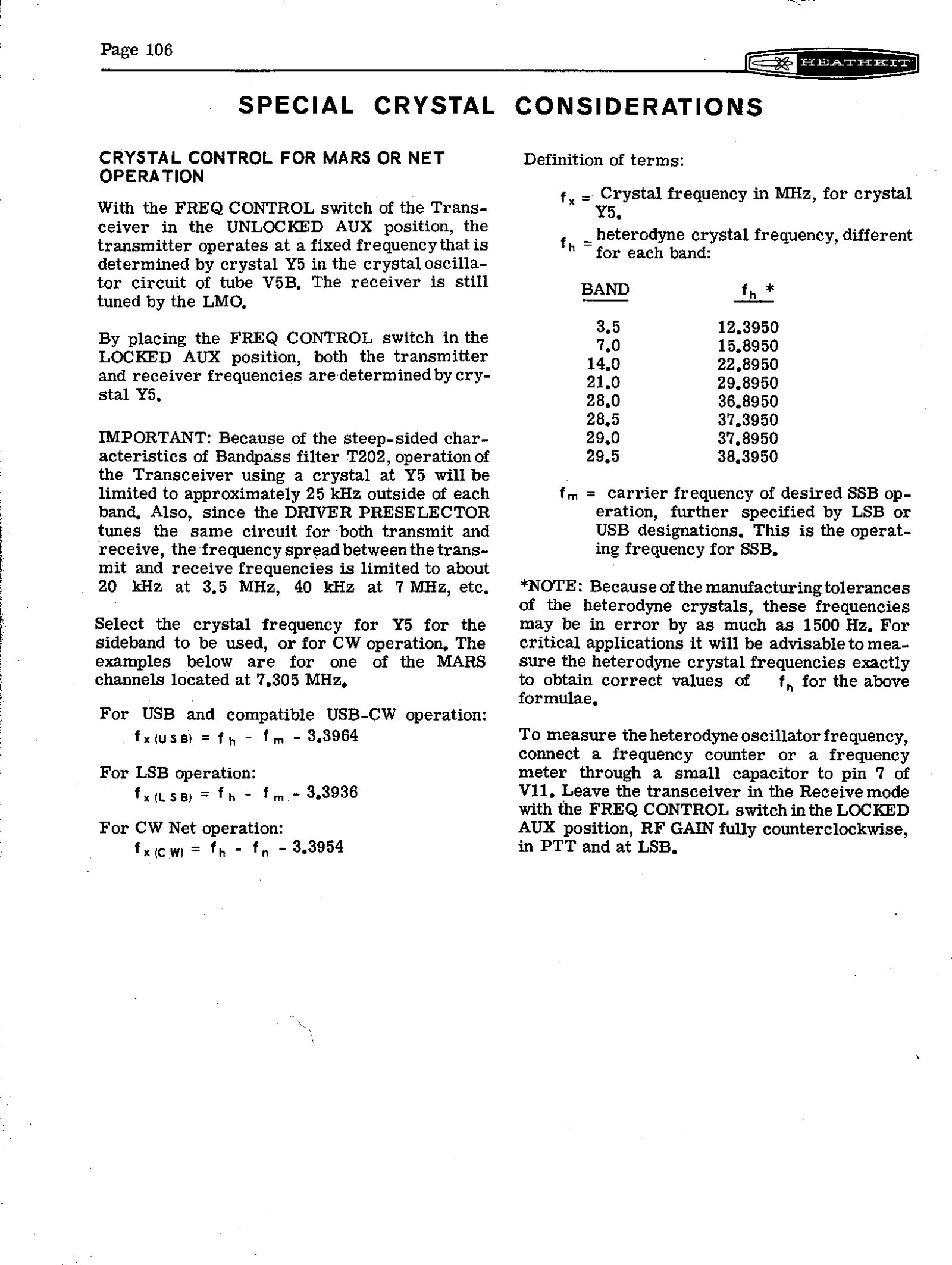
The special-crystal pages are unique to the SB transceivers and explain how to use the FREQ CONTROL switch’s AUX positions. A crystal in socket Y5, a fundamental-mode HC-6/U crystal in the LMO’s 5.0–5.5 MHz range, sets the frequency. It is worked out from the heterodyne crystal for the band, fh, and the wanted carrier frequency, fm, all in MHz:
Table 1 — The special-crystal pages are unique to the SB transceivers and explain how to use the FREQ CONTROL switch's AUX positions. A crystal in socket Y5, a fundamental-mode HC-6/U crystal in the LMO's 5.0–5.5 MHz range, sets the frequency. It is worked out from the heterodyne crystal for the band, fh, and the wanted carrier frequency, fm, all in MHz
| Operation | Crystal frequency |
|---|---|
| USB, and compatible USB-CW | fh − fm − 3.3964 |
| LSB | fh − fm − 3.3936 |
| CW net | fh − fn − 3.3954 |
The manual’s worked example is a MARS channel on 7.305 MHz USB: 15.8950 − 7.3050 − 3.3964 = 5.1936 MHz. It also specifies the crystal in full: 0.01 per cent tolerance, 32 pF load, 25 Ω maximum series resistance and 10 mW drive. A trimmer beside the socket, AUX TRIM, pulls it onto the exact channel. Two cautions follow. The heterodyne crystals themselves may be off by as much as 1500 Hz, so for critical work the builder should measure the one in use at pin 7 of V11. And changing MODE while on a crystal moves the transmitted frequency, except in compatible USB-CW operation, so a careless mode change can put the transmitter outside the band.
4.7 The controls
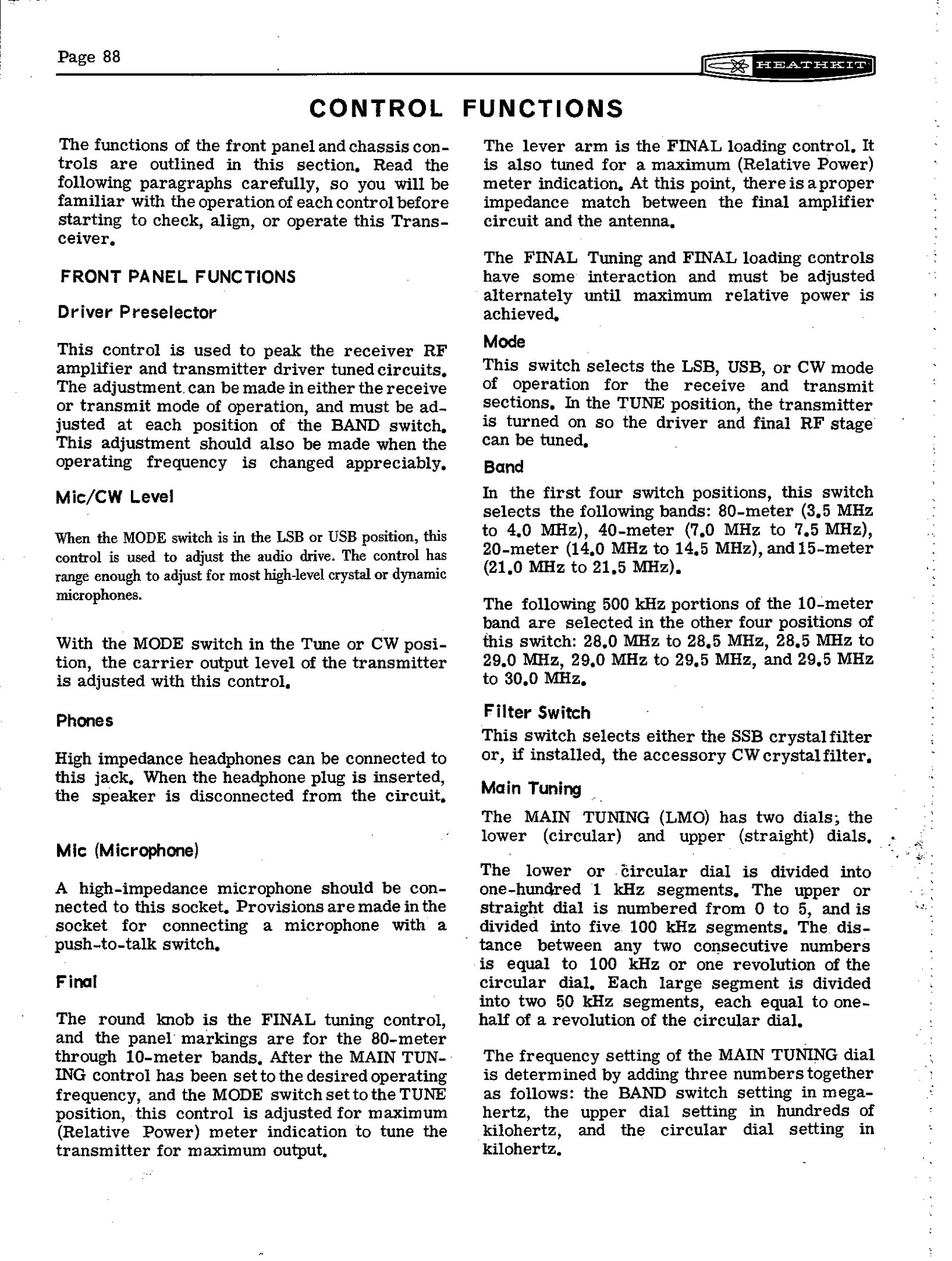
Front panel. Main tuning (the LMO); the zero-set dial; DRIVER PRESELECTOR; FINAL tuning (round knob) and loading (lever); MIC/CW LEVEL; MODE (LSB, USB, CW, TUNE); BAND (eight positions); FUNCTION (OFF, PTT, VOX, CAL); FREQ CONTROL (LOCKED NORMAL, LOCKED AUX, UNLOCKED AUX); METER (GRID, PLATE, ALC, REL PWR, HV); RF GAIN, with the FILTER switch lever on the same shaft; AF GAIN; and the PHONES and MIC jacks.
Under the hinged lid. VOX SEN, VOX DELAY and ANTI-TRIP on a control bracket; METER ZERO; CARRIER NULL; CW-TONE VOLUME; PHONE VOL, which balances headphone level against the speaker; BIAS ADJUST; and RELATIVE POWER.
Rear apron. CW KEY; 8 Ω speaker; phone patch input; ALC input from a linear; the 11-pin power plug; RF OUT; DRIVER OUTPUT, for the SB-500 two-metre transverter; and two spare phono sockets.
4.8 Reading the frequency
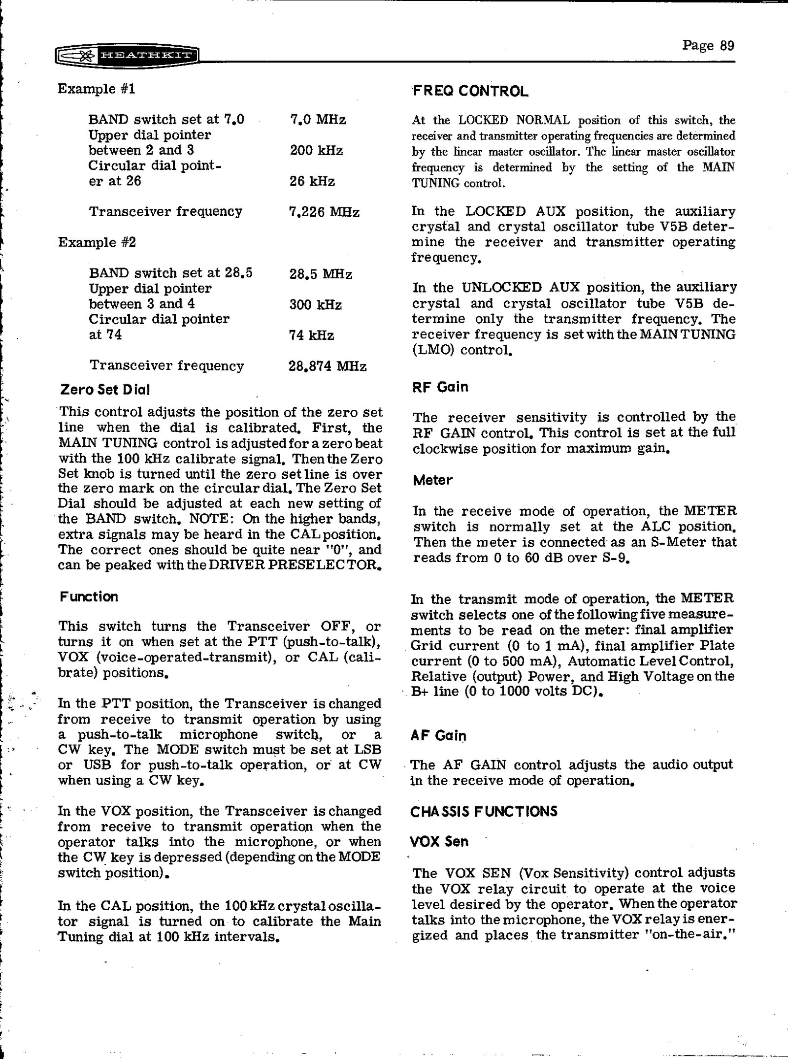
The operating frequency is the sum of three numbers: the BAND switch setting in megahertz, the slide-rule pointer in hundreds of kilohertz, and the circular dial in kilohertz. The manual’s two examples are 7.0 + 0.2 + 0.026 = 7.226 MHz, and on 10 metres 28.5 + 0.3 + 0.074 = 28.874 MHz. The band switch marks each 10-metre segment with its starting frequency, 28.0, 28.5, 29.0 or 29.5, so the same addition works on every position. Before trusting a reading, the operator switches to CAL, tunes the nearest 100 kHz point to zero beat, and sets the zero-set dial’s hairline over 0. The manual adds that on the higher bands spurious calibrator signals appear, and that the genuine ones peak with the DRIVER PRESELECTOR.
4.9 Reading the meter
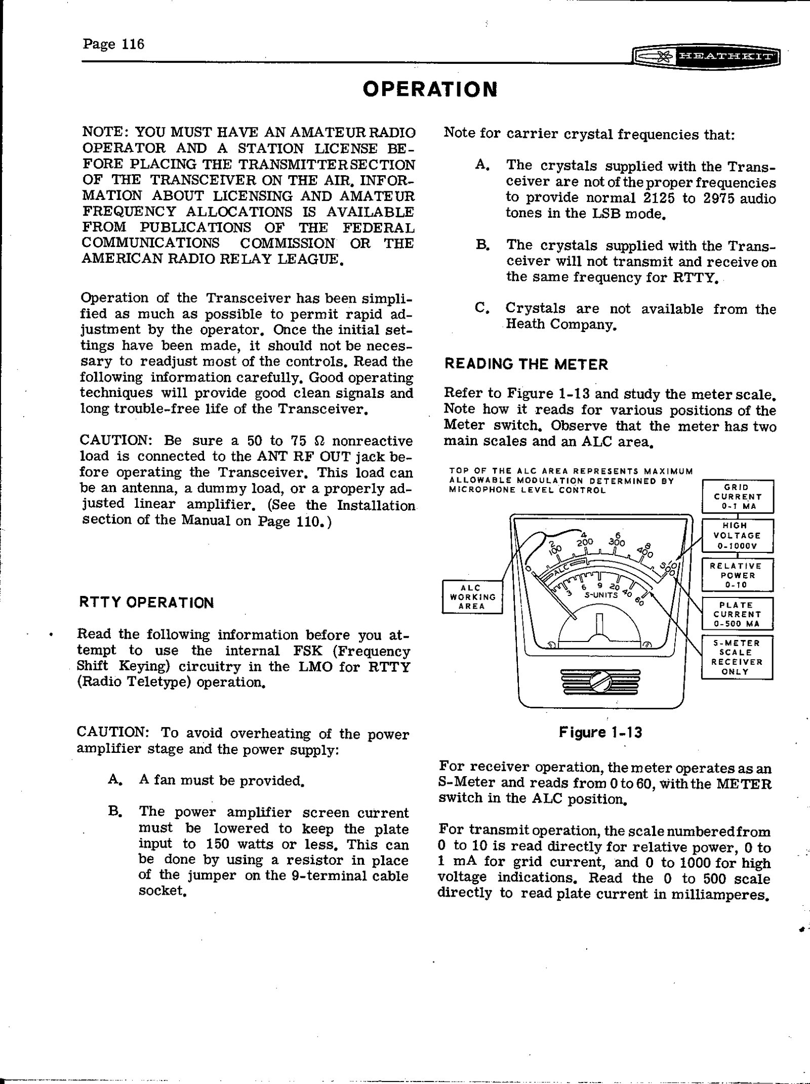
On receive, with the METER switch at ALC, the meter is an S-meter reading 0 to 60, the scale above S9 in decibels. It still reads correctly with the RF GAIN backed off, provided the signal is strong enough to register. On transmit, the 0–10 scale reads relative power directly, 0–1 mA of grid current, and high voltage as 0–1000 volts. The 0–500 scale reads plate current in milliamperes. The ALC area at the left of the scale marks the top of the permissible modulation: when the MIC level is set correctly, voice peaks swing into it and not beyond.
4.10 Tuning up
The manual’s initial tune-up is the same for every mode.
- Set the band and frequency, METER to PLATE, MIC/CW LEVEL fully anticlockwise and FREQ CONTROL to LOCKED NORMAL.
- With a load on RF OUT, switch to TUNE; the meter should read the 50 mA idling current.
- Set METER to REL PWR, the loading lever to 50, and FINAL tuning to the band in use.
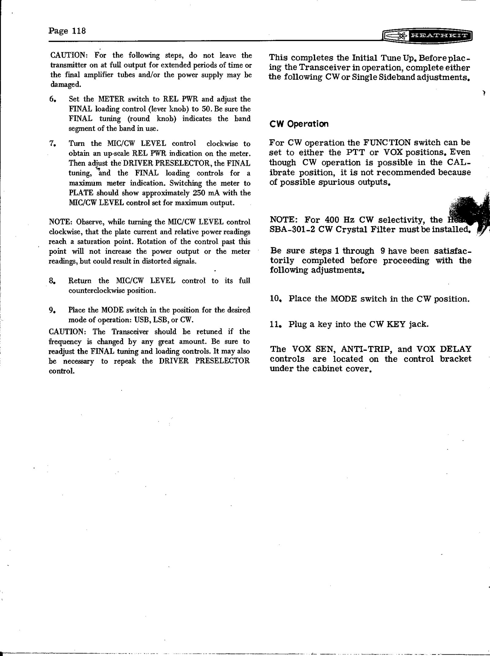
- Advance MIC/CW LEVEL until relative power shows. Peak the DRIVER PRESELECTOR, FINAL tuning and FINAL loading for maximum. On PLATE the meter should show about 250 mA with the level control set for maximum output.
- Return MIC/CW LEVEL to zero and choose the mode.
The manual warns against leaving the transmitter at full output “for extended periods of time”, for the sake of both the finals and the power supply. It also notes that plate current and relative power reach a saturation point, beyond which turning the level control further only distorts the signal. The rig should be retuned whenever the frequency is changed “by any great amount”.
4.11 On the air
SSB. FILTER to SSB, METER to ALC, and the MIC/CW LEVEL advanced while speaking until peaks reach about S-6 on the meter, within the ALC area. VOX is set with the level control off. VOX SEN is set just past the point where speech keys the relays, ANTI-TRIP just past the point where speaker audio no longer trips them, and VOX DELAY long enough to hold through the pauses between words. The manual notes that the three interact and recommends close-talking the microphone.
CW. A key in the CW KEY jack, MODE at CW, FUNCTION at PTT or VOX. CW works through the VOX circuit, keyed by the internal tone, so VOX DELAY sets the hang time: the manual suggests sending a string of Vs and setting it so the relays hold between groups. CW TONE VOLUME sets the sidetone. The transmitted CW signal is 1000 Hz higher than the dial reading, and on receive the rig is effectively on USB. The manual points out the consequence: two stations can work each other with one on USB and the other on CW, without retuning. With the SBA-301-2 filter fitted, either filter position can be used for receiving CW; transmission is unaffected.
With a linear amplifier. Heath’s own SB-200 and SB-220 supply ALC back to the exciter and switch their own antennas. The transceiver’s spare relay contacts, rated 3 A at 30 V DC or 120 V AC, key the amplifier through the power plug or a jumper to a spare rear-panel phono socket. For an amplifier that needs only about 10 watts of drive, the manual gives a 10 dB, 50 Ω T-pad to go between the two.
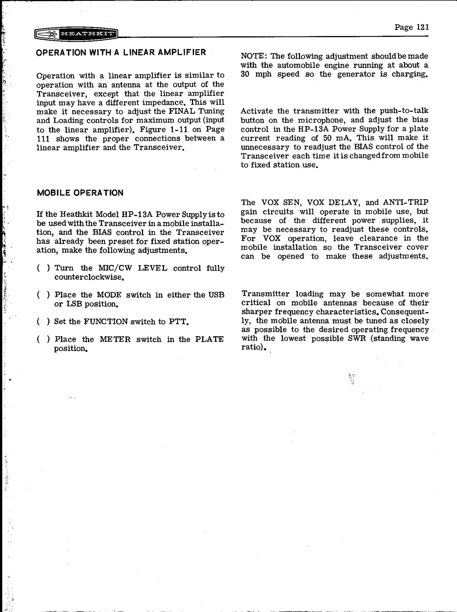
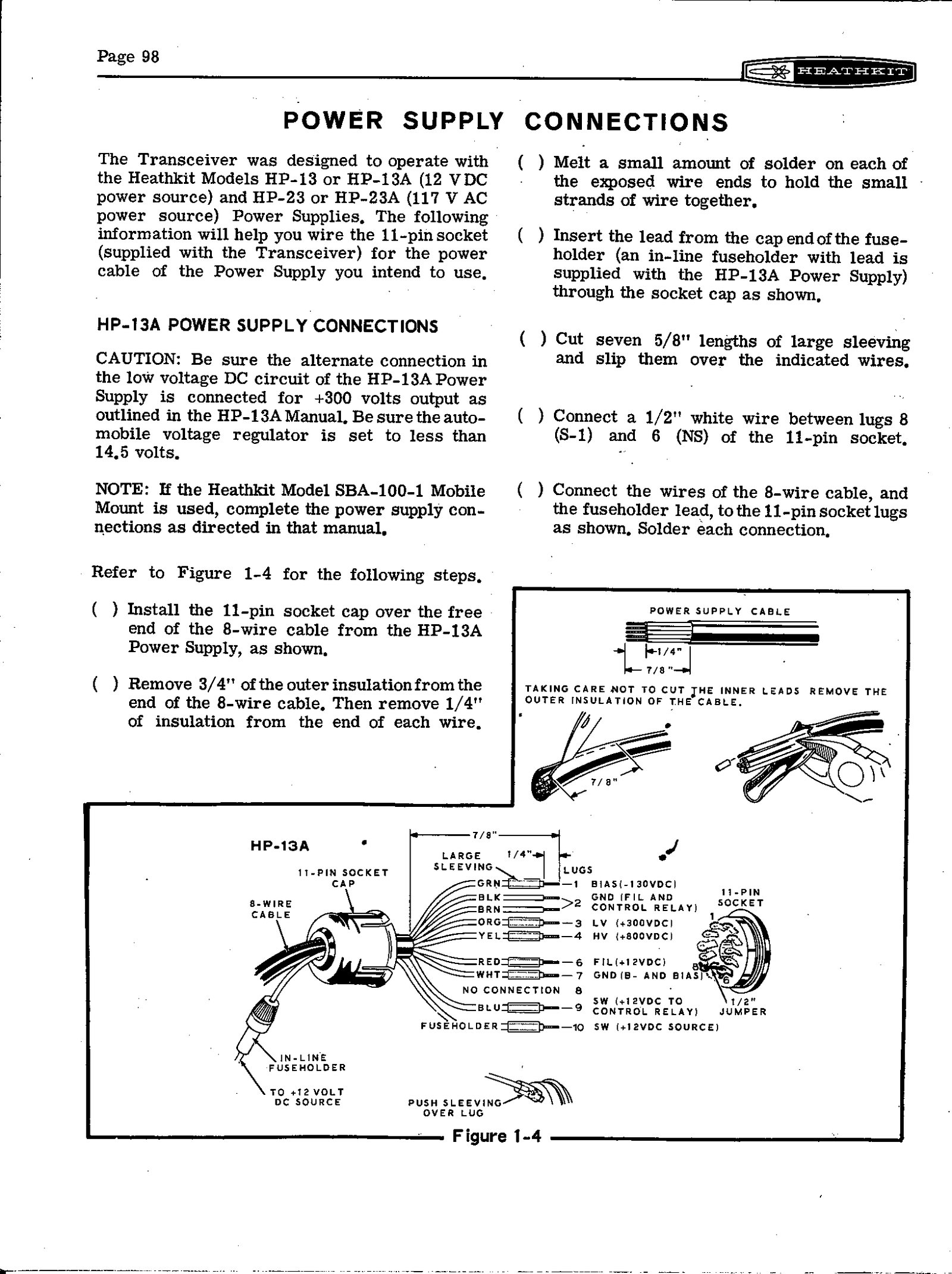
Mobile. With the HP-13A supply, the car’s voltage regulator must be set below 14.5 volts. The supply’s own bias control is set once for 50 mA of idling current with the engine charging, so that the transceiver’s BIAS ADJUST need not be touched when the rig moves between car and shack. The SBA-100-1 mount lets the rig be lifted out. The manual’s antenna notes are practical: a good 75-metre whip has only about 10 kHz of useful bandwidth either side of resonance, and it may need a 1000 pF mica capacitor across the feed point to reach 50 Ω.
RTTY. The LMO’s FSK terminal makes frequency-shift keying possible, but the manual’s conditions are strict. A fan must cool the finals and the supply, and the plate input must be held to 150 watts or less by replacing a jumper on the 9-terminal cable socket with a resistor. It also warns that the supplied carrier crystals will not produce the standard 2125/2975 Hz tones in LSB or transmit and receive on the same frequency, and that suitable crystals “are not available from the Heath Company”.
Sources
- Heathkit Assembly Manual, SSB Transceiver Model SB-102, 595-1058-06 (Heath Company, 1970): Control Functions pp. 88–90, Power Supply Connections pp. 98–99, Initial Test p. 100, Alignment pp. 101–105, Special Crystal Considerations pp. 106–107, Installation pp. 110–115, Operation pp. 116–121, Specifications pp. 131–134. W5RKL scan · Internet Archive (pp. 88 onward)
- W5RKL, “SB-102 Alignment and Schematic” (extract). PDF
- Kembel, Robert W. (W5RKL), Mark (WB8JKR) and contributors. Heathkit HW-101 and SB-10x Restoration and Troubleshooting, revised 17 December 2021, sections a.3.6 and e (alignment). PDF
- Lutz, Joseph W. (W7LPF). “Heathkit Service Bulletins: SB-102,” 1998, bulletins SB-102-8 (alternate neutralizing method) and SB-102-18 (carrier null). Archive
Comments (0)