SB-102 Transceiver · Volume 5
Restoration and Common Faults
An SB-102 that has sat unused for decades is usually recoverable. The tubes it uses are still made or plentiful, the circuit is fully documented, and the one part that cannot be bought new, the sealed LMO, is also the one part that seldom fails outright. What goes wrong with these rigs is what goes wrong with any tube equipment of the period — electrolytic capacitors, drifting carbon-composition resistors, weak or leaky tubes, dirty switches and relay contacts — plus a short list of faults peculiar to the SB family: the plastic dial, the rubber belts on the preselector drive, the mounting of the LMO, and some well-documented tube-brand sensitivities. The HW-101 shares most of these, and the HW-101 dive’s restoration volume covers the common ground from that rig’s side. This volume concentrates on the SB-102.
The single most useful document for this work is the Heathkit HW-101 and SB-10x Restoration and Troubleshooting manual compiled by Mark (WB8JKR) and hosted by Mike Kembel (W5RKL), a 190-page collection of procedures, measurements and modifications revised to December 2021. It is cited below as the restoration manual (PDF).
5.1 Safety, first and repeatedly
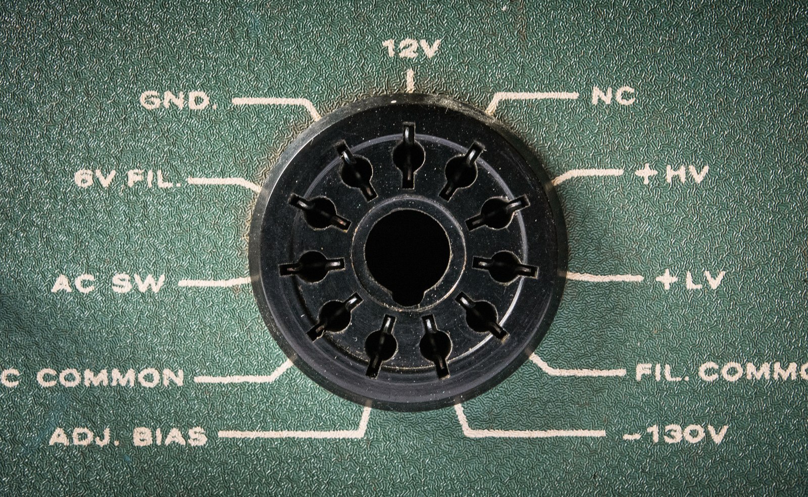
The SB-102 has no power supply inside it. All of its voltages arrive through the 11-pin plug from an HP-23 series supply, and the finals’ plate line runs at 800 to 900 volts, well above a lethal level. Four rules follow from that and from the manual:
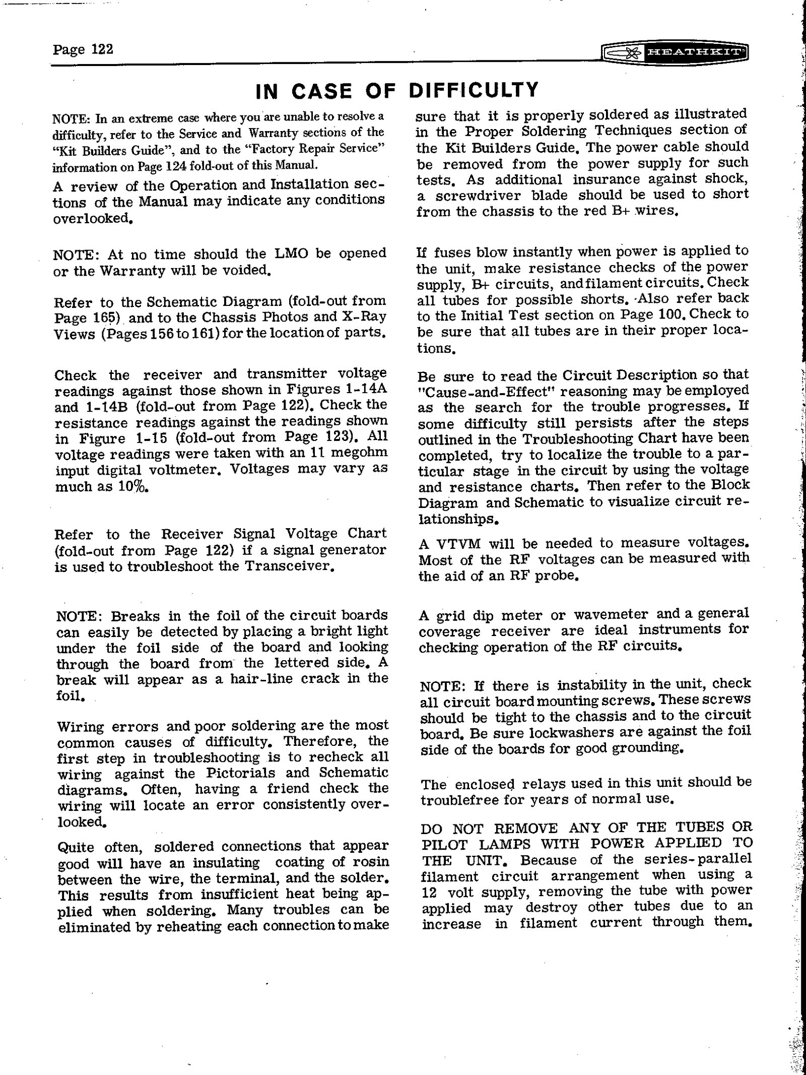
- The supply keeps its charge. Unplugging the transceiver does not make it safe while the power cable is connected to a charged supply. The assembly manual’s own advice, when resoldering joints during troubleshooting, is to remove the power cable from the supply and then short the red B+ wires to the chassis with a screwdriver blade “as additional insurance against shock”.
- The cabinet off means the high voltage exposed. Every adjustment in the alignment is made with the rig powered and the covers off, above and below the chassis. Heath’s instructions are an earth lead from a good ground to the chassis and every piece of test equipment, and well-insulated alignment tools.
- Never pull a tube or pilot lamp with power applied. In mobile use the 12-volt heaters are wired series-parallel, and removing one tube with power on can destroy others by overloading their heaters.
- Never transmit without a load. The manual requires a 50 to 75 Ω non-reactive load on RF OUT before the transmitter is used. That means an antenna, a dummy load or a properly adjusted linear, and never light bulbs.
The HP-23 supply needs the same caution and its own restoration: its filter capacitors are the oldest and most stressed components in the station. The supply family is covered in the HW-101 dive.
5.2 Buying and first assessment
Two points follow from the SB-102 being a kit. First, every example was assembled by a different builder, and some were never right. Kees (K5BCQ)‘s advice for the solid-state SB-104, “don’t automatically assume a complex kit is wired correctly”, applies equally here (K5BCQ). Second, most have been worked on since. The things worth checking before buying, or before first power-up, are these:
- The dial. It should turn smoothly through five full revolutions from stop to stop, with the slide-rule pointer stepping once per turn. The plastic circular dial should be free of cracks in its visible area. Eckweiler’s advice is to check it first, because a dial that is not physically broken can usually be made smooth again (Heathkit of the Month #30).
- The LMO. It should not have been opened. If the seals are disturbed, its calibration and linearity can no longer be assumed.
- The serial number. Sets below 5446 predate the Miller-effect correction in the driver and may or may not have had the SBM-102-1 kit fitted.
- The underside. The harness should be neat, with no long free-standing leads, no bridged solder, and nothing obviously replaced by a later hand.
- The environment it came from. One eHam reviewer abandoned a set “essentially destroyed by corrosive tobacco smoke”; another describes the owners who are disappointed with the model as those who expected a 50-year-old rig from a dirty garage to work without an overhaul (eHam reviews).
5.3 Bringing one up
The restoration manual’s checklist for the SB-10x series is thorough, and in outline it runs as follows.
- Record the set. Start a log of the model, serial number, condition and modifications.
- Clean. Vacuum and brush the chassis; clean the front panel with soap and water only, because stronger cleaners lift the lettering; clean the circular dial with water only.
- Inspect. Look for burned resistors and bulging capacitors. A burned R701 or R940 usually means a band-switch lug has touched the coil cover.
- Replace the electrolytics. The restoration manual lists the two 20 µF 450 V capacitors, C304 on the audio board and C12 on the modulator board; the two 10 µF 50 V capacitors, C2 on the modulator board and C212 on the bandpass board; and, on the SB-102 only, the two 500 µF 25 V capacitors C941 and C942 in the LMO supply.
- Tighten and clean. Tighten every circuit-board screw; both the manual and the restoration guide stress that the lockwashers must bear on the foil, because the boards are grounded through them. Clean the tube shields and their grounding tabs at the transmitter mixer and driver, whose poor contact is “almost guaranteed to cause transmit instability”. Clean the relay contacts with a strip of card moistened with contact cleaner.
- Tubes. Test every tube, clean the socket pins, and tighten loose socket contacts.
- Mechanics. Lubricate the controls and switches, the shaft bushings and the SSB/CW filter-switch mechanism. Replace the rubber belts on the DRIVER PRESELECTOR and loading drives. Oil the LMO’s follower pawls and confirm its full five-turn travel.
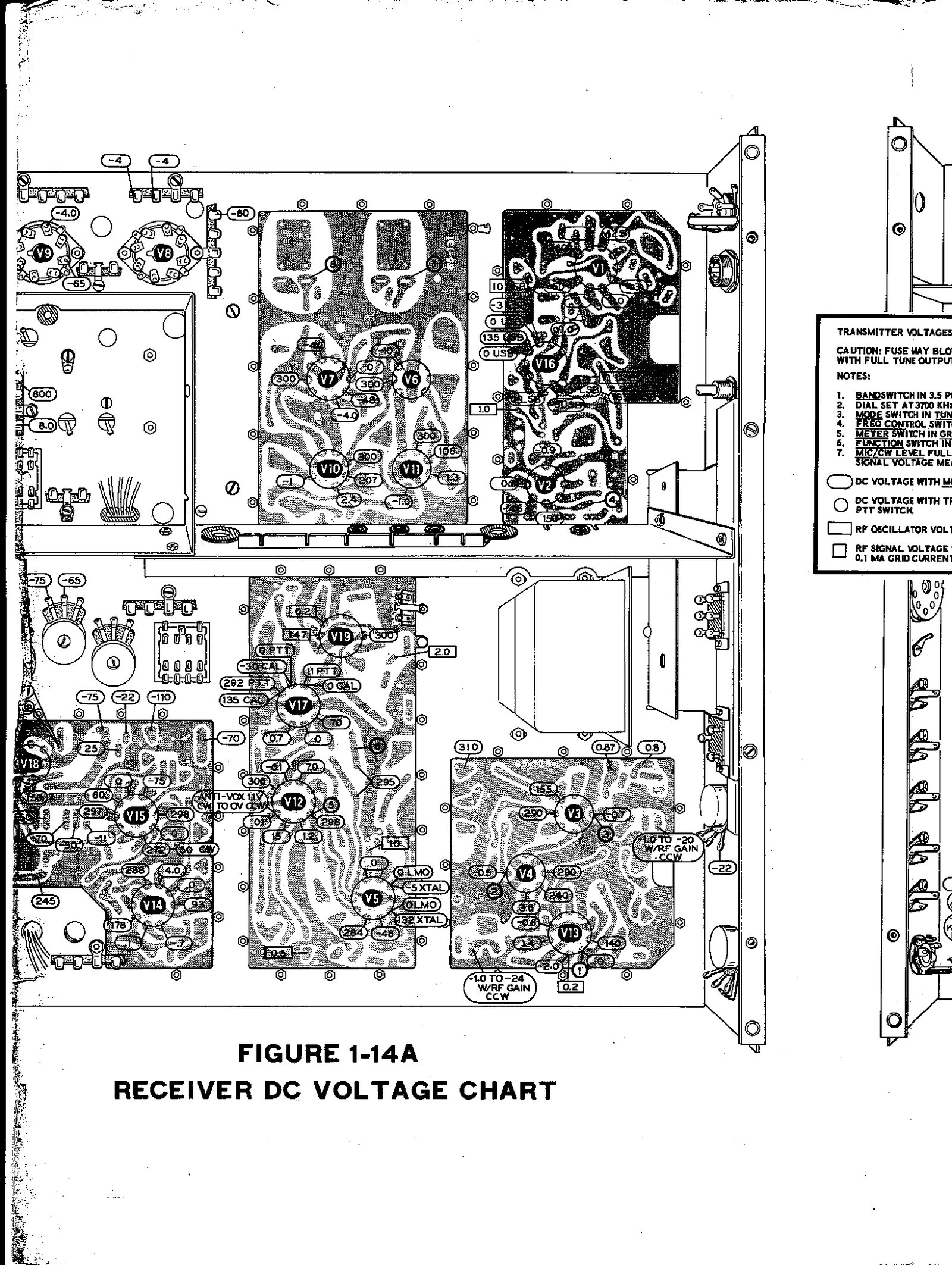
- Check before power. Before any power is applied, work through the manual’s resistance charts. Those readings were made with a VTVM. The voltage charts were taken with an 11 MΩ digital voltmeter and may vary by 10 per cent.
The restoration manual also recommends switching vintage equipment from a power strip rather than its own power switch, to spare switches that are now hard to find. A variac or a series lamp for the first power-up of a long-idle supply is general good practice. One eHam owner describes running two newly acquired SB-102s continuously for 24 hours after a slow bring-up; both then aligned without trouble.
5.4 What actually goes wrong
5.4.1 Tubes, and which brands
A surprising number of the factory’s service bulletins are about tubes, and several name brands. The bulletins themselves were not examined for this dive; the summaries below come from a list compiled by Joseph Lutz (W7LPF) and posted to the Heath mailing list in 1998 (archive).
Table 1 — Tubes, and which brands
| Bulletin | Date | Symptom | Remedy |
|---|---|---|---|
| SB-102-2 | 14 Sep 1972 | Repeated heterodyne oscillator tube failure | R212 from 220 Ω to 330 Ω |
| SB-102-3 | 23 Mar 1973 | Low grid drive, alignment problems | Use RCA 6146 finals; revised alignment |
| SB-102-14 | 5 Jun 1978 | Relays stay energised after transmit | Replace V12 (6EA8); IEC tubes found defective |
| SB-102-15 | 5 Jun 1978 | Poor AGC and sensitivity | Leakage in the 6HS6 |
| SB-102-19 | 7 Aug 1978 | Relays chatter on VOX | Avoid GE 6EA8 at V1 |
| SB-102-22 | 22 Aug 1978 | S-meter drift | Isolate a leaky tube at V3, V4, V10 or V11 |
| SB-102-24 | 25 Apr 1979 | Low output, poor VOX sensitivity | Avoid Sylvania, RCA and Westinghouse at V3/V4 |
| SB-102-30 | 21 Sep 1984 | S-meter drift, IF oscillation | GE 6AU6 at V3 and V4 only |
The 6HS6 RF amplifier deserves its own note. The restoration manual reports that the circuit runs it “at or, in some cases, exceeding the tube’s ratings”, that shorted 6HS6s are a common failure, and that the symptom is unmistakable: total loss of sensitivity with a strong “20 over 9” meter reading of static, with or without an antenna connected. A 6AU6 plugs in as a direct substitute with no circuit change, at some cost in gain. The SB-102 has one 6HS6, at V10; the first receiver mixer V11 is a 6AU6 (restoration manual, section a.3.1).
The finals are ordinary 6146s. The HW-101’s service bulletins warn that the later 6146B can overheat the plate choke and resist neutralisation on 10 and 15 metres in these circuits; the HW-101 dive gives the details. For the SB-102, the only factory bulletin on the finals found is SB-102-3’s recommendation of RCA 6146s. The audio tube, a 6GW8, is the ECL86 in European numbering, and restorers’ discussions point to the ECL86 as the practical replacement (Antique Radio Forums thread).
5.4.2 Resistors, capacitors and meter zero
Carbon-composition resistors drift high with age, and paper and electrolytic capacitors leak. One restorer documented 15 out-of-tolerance resistors and an electrolytic leaking 3.6 mA at its rated voltage in a single SB-102, along with a faulty 100 kHz calibrator crystal that caused scratchy audio. His list of likely faults, in order of probability, is: tubes, ground connections, dirty switches, solder joints, wiring errors, leaky capacitors and drifted resistors (Nostalgic Kits Central).
S-meter zero that wanders is a recognised fault with a known cause. The restoration manual traces it to heating of R106, a 22 kΩ 1-watt resistor on the IF board. Its advice is to replace R106 with a 2-watt wirewound or other non-carbon type and to uprate R107. The SB-102’s later IF board, 85-128-5, already has R106 at 33 kΩ, a change the restoration manual says was made to improve the life of V3, with R110 changed to 510 Ω so that the meter can still be zeroed. Heath’s own first bulletin for the model, SB-102-1 of November 1970, changed R107 from 100 kΩ to 82 kΩ to bring the meter-zero range within the control’s tolerance.
5.4.3 The dial
The plastic circular dial is the SB family’s weak point, and owners’ complaints about it are consistent: “did anyone have a dial that didn’t get the hairline crack(s)?” asked one reviewer, whose replacement from the Heath parts department also arrived cracked (eHam reviews). The restoration manual collects the repairs:
- Cracks. Cracks outside the visible area can be stopped with a little cyanoacrylate glue applied only on the flat side of the dial, never on the spiral groove or the numbered face. A dial whose hub has broken out has been rebuilt by gluing it, clamping it with a stainless hose clamp, and filling the hub pocket.
- The spiral groove. It needs cleaning and a light silicone lubricant, and the nylon follower should be inspected and replaced if worn.
- Uneven drag. Drag that grows toward the “5” end of the slide rule has been traced to the dial sitting slightly cocked on the LMO shaft. The setscrew pushes the hub off-centre where there is too much clearance between hub and shaft, so the spiral groove moves in and out and the follower binds.
- The zero-set dial. A zero-set dial that slips usually has a loose pinch roller, made of two spring washers. It is often damaged by someone pulling the front panel off without knowing the roller must stay with the dial. A floppy zero-set window has lost the clip that holds it to the tuning hub.
- The pinch roller. Slipping is cured by cleaning the metal ring and roller, then by adding a little grip, for example a thin coat of silicone.
5.4.4 The preselector and loading drives
The DRIVER PRESELECTOR and FINAL loading capacitors are turned through rubber belts, which perish. Service bulletin SB-102-17 (July 1978), “Poor Preselector Tracking”, tells the servicer to check the drive belt for slipping and lubricate the variable capacitor’s bearings. SB-102-20, “Loading Capacitor Turns During Tuning”, added a rubber grommet to the loading shaft for friction. Replacement belts are the commonest mechanical repair on these rigs.
5.4.5 The LMO
The LMO seldom fails outright, but several problems are documented.
- Instability from its mounting. Service bulletin SB-102-4 (March 1973) found that the lockwashers and nuts holding the LMO to the chassis allowed instability. Heath replaced them with flat washers and hex lock nuts, tightened a turn at a time in a criss-cross pattern, and recommended the change on every SB-102 that came in for service, whether or not the owner had reported a problem.
- Stiff or short travel. In the tube LMOs, hardened grease on the stop washers can stop the dial short of its five turns, and a restorer has published the dismantling procedure for an SB-301’s LMO. Whether the SB-102’s transistor LMO has the same stop mechanism has not been confirmed. Stiffness that cleaning and fresh grease cannot cure means removing the LMO, which the restoration manual shows can be done without taking off the front panel.
- Warble while tuning. Ageing tube LMOs often “warble” while the knob is being turned, because the lubricant at the tuning capacitor’s pivots breaks down. K9STH’s repair, in the restoration manual, adds a ground braid to the capacitor rotor. Whether the SB-102’s transistor LMO suffers the same way is not documented in the sources examined.
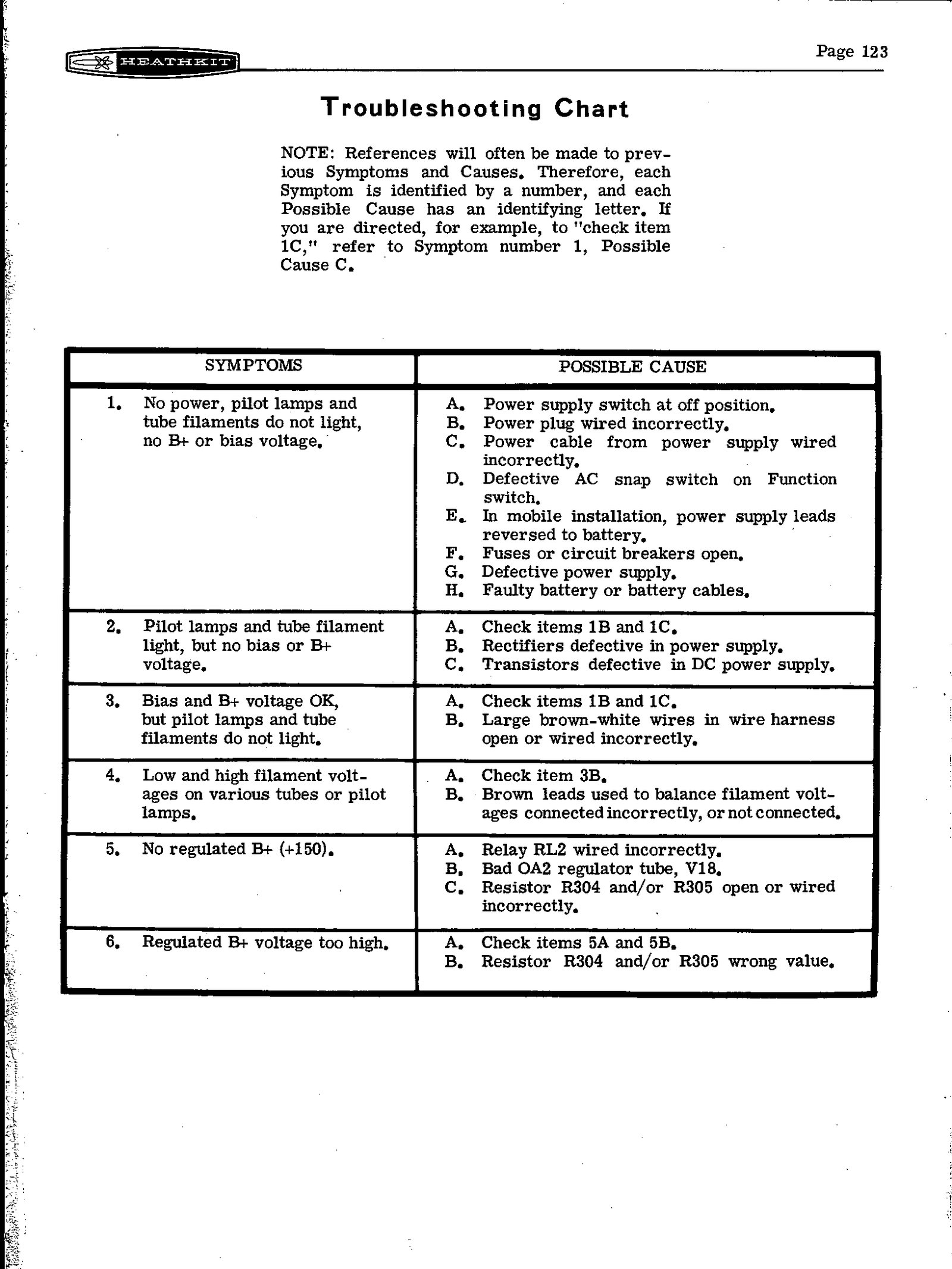
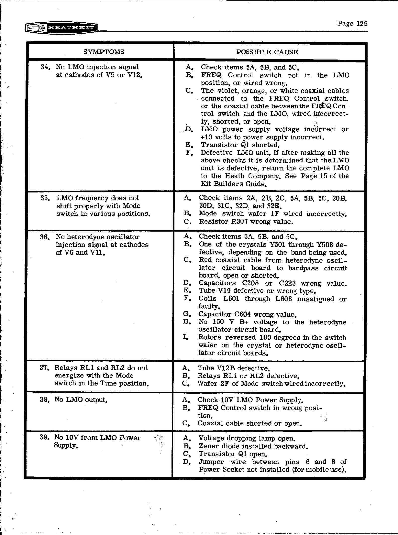
- Its supply. An LMO that is silent or erratic may simply be short of its 10 volts. The chain to check is the rectifier, C941 and C942, the pilot lamp that acts as the dropping resistor, the zener, and the 2N3567 switch. The manual’s troubleshooting chart item 39 lists “voltage dropping lamp open”, “zener diode installed backward”, “transistor Q1 open” and, for mobile use, a missing jumper between pins 6 and 8 of the power socket.
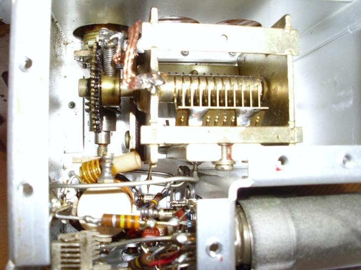
The restoration manual’s author advises against swapping LMOs between models. The SB-101 and SB-102 LMOs differ in supply and sideband-shift circuitry, and “messing around with swapping LMO’s could result in instability that you didn’t have before.”
5.4.6 Instability and oscillation
A cluster of bulletins from 1973 to 1975 dealt with transmitter instability:
- SB-102-5, “Low 40 Meter Output”. It removed a short bare wire that joined the driver plate board to the ground foil of the RF-driver board.
- SB-102-7. A 25-point instability checklist covering solder joints, shielding and alignment.
- SB-102-9 (December 1974). Aluminium comb brackets were replaced with steel ones, part 204-2096, and both shields were soldered.
- SB-102-10 (May 1975). Oscillation that appeared after the steel-bracket change was cured by tightening the RF-driver board screws, with a reminder that the lockwashers between board and chassis “must be installed”.
The pattern throughout is grounding. Heath’s circuit boards are grounded through their mounting screws and lockwashers, and a loose screw or a missing lockwasher is a common cause of oscillation. The manual’s troubleshooting chart makes the same point under item 42, as does the restoration checklist.
5.4.7 Switches, relays and the filter switch
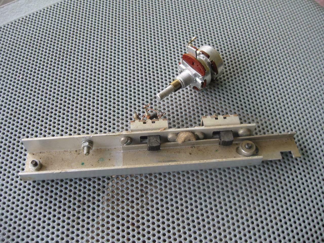
Dirty contacts account for a range of vague faults. Bulletin SB-102-21 attributes “chirping” and slow receiver recovery to carbon and dirt on relay RL2’s contacts, which carry the bias and AGC lines. SB-102-25 found that grease and dirt on the SSB/CW filter slide switch “can affect” both transmitter and receiver performance. Bulletin SB-102-23, “Poor IF Sensitivity”, identifies a common assembly error to look for in any kit-built example: C101 connected to point 2 instead of point 15 on the IF board.
5.5 Modifications
The restoration manual’s modification section is written around the HW-101 but, as its author notes, applies equally to the SB series. The modifications worth knowing about on an SB-102 are:
- The SBM-102-1 kit. Heath’s own Miller-effect fix for the driver, standard on later SB-102s. On an early set without it, the parts are common and the seven-page instruction sheet circulates, according to Eckweiler.
- The antenna connector. The RCA phono RF OUT jack can be replaced with a bulkhead BNC or an SO-239. K5BCQ, writing about the later SB-104, argues that a bulkhead BNC is electrically and mechanically better and needs no chassis change.
- Low-impedance headphones. A rewiring of the headphone jack so that modern low-impedance headphones mute the speaker completely.
- Meter-zero stability. The R106 and R107 changes described above.
- An external VFO. The SB-102’s FREQ CONTROL switch already routes an external oscillator for split operation; the restoration manual shows how any 5.0–5.5 MHz source can stand in for an SB-640.
- The SB-100 CW filter. An SB-100 can be given the SB-101 and SB-102’s front-panel filter switching by transplanting the smaller filters, their bracket and the RF GAIN control with its filter-switch lever from a parts chassis.
5.6 Cosmetics
The SB-102’s cabinet and panel are painted steel and aluminium in Heath’s grey and green. The panel lettering is fragile, which is why the restoration manual limits front-panel cleaning to warm soapy water. For repainting, the manual’s contributor reports good results with Sherwin-Williams acrylic matched from an original part, and textured Rust-Oleum finishes as undercoats. He also gives a mixing formula for the lighter green of the SB-104 generation. The knobs and meter bezel clean up with mild detergent.
5.7 Parts, today
Almost everything in an SB-102 except the LMO and the crystals is a standard part. The 6146, 6AU6, 6EA8, 6GW8/ECL86, 12AT7, 12AU7 and OA2 are all available from tube suppliers, and the 6HS6 is available at a higher price or can be replaced by a 6AU6. Capacitor kits specific to the SB-101 and SB-102 are sold commercially (W8AOR). Replacement dials, dial parts, belts and knobs come from parts chassis and from restorers who reproduce them. The 400 Hz SBA-301-2 filter is shared with the SB-101, SB-301, SB-303 and HW-101, so used filters turn up. Eckweiler warns that the later SBA-104-3 CW filter for the SB-104 has a different centre frequency and is not a substitute. The Heath Company’s current owner sells paper reprints of manuals; free scans are listed in the Reference volume.
Sources
- Heathkit Assembly Manual, SSB Transceiver Model SB-102, 595-1058-06 (Heath Company, 1970): In Case of Difficulty p. 122, Troubleshooting Chart pp. 123–130, voltage and resistance charts. W5RKL scan
- Kembel, Robert W. (W5RKL), Mark (WB8JKR) and contributors. Heathkit HW-101 and SB-10x Restoration and Troubleshooting, revised 17 December 2021. PDF
- Lutz, Joseph W. (W7LPF). “Heathkit Service Bulletins: SB-102,” Heath mailing list, 3 April 1998. Archive
- Eckweiler, Bob (AF6C). “Heathkit of the Month #30: The Amateur Radio SB-Line Overview,” 2011. PDF
- Nostalgic Kits Central, “Heathkit SB-100-102 Info”. Link
- K5BCQ, “SB-101/102 Repair Site” and SB-104 repair pages. SB-101/102 · Home
- eHam.net, Heathkit SB-102 reviews. Link
- Antique Radio Forums, “The beginning of a Heathkit SB-102 restoration” (thread). Link
Comments (0)