HERO 2000 (ET-19) · Volume 8
I/O, Communications & Programming
8.1 What this volume covers
The HERO 2000 has a hexadecimal keypad on its head, but it is not a robot meant to
be programmed by thumbing hexadecimal into it. It is a robot built to be developed
against from a desk — wired to a
terminal and a printer over two serial ports, talked to across the room by a
wireless remote and a two-way radio link, storing its work on floppy disk, and
programmed in a full BASIC that lives permanently in ROM. Where the HERO 1 and the
HERO Jr offer a single optional serial channel and lean on a keypad or cartridge
for their programs, the HERO 2000 carries a host-development workflow as a
first-class feature of the machine (hero.dsavage.net HERO 2000 spec sheet;
theoldrobots.com; selectric.org).
This volume walks the input/output layer — the two RS-232C ports, the remote console and keyboard, the radio data link, the 16 head LEDs, and the floppy controller — and then the programming model that sits on top of it: HERO 2000 BASIC resident in ROM, assembly-language development, and the Heath/Zenith Educational Systems course that taught both. The actual language syntax — keywords, statement forms, the I/O command set — belongs to the factory ET-19 Programming Manual, and is deferred to it throughout; this volume describes the plumbing and the workflow, not the dialect.
8.2 The communications slave processor
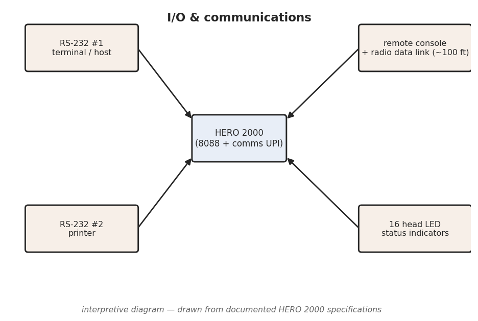
Like every other subsystem on the HERO 2000, communications is not run directly by the main processor. The Intel 8088 master delegates it to a dedicated Intel 8042 UPI slave processor — the communications slave — one of the set of peripheral microcontrollers described in Vol. 2 (HERO 2000 spec sheet). Alongside that slave the spec sheet lists a 2661 serial controller (cited in the architecture notes as a 2661-2), the hardware UART that frames the bytes on the wire. The division of labour matters for how the machine feels to use: the 8088 can be running a user program, or stepping the drive servos, while the communications slave independently keeps a terminal session alive and a printer fed. Real-time serial work does not steal cycles from the program the way it would on a single-processor robot.
This is the same delegation pattern that defines the whole machine — motor control, sonar, the keypad/display, and (with the arm) the arm motor each have their own 8042 — and the communications slave is simply the one that owns the outside world. Vol. 2 covers the master/slave architecture and the passive backplane in detail.
8.3 The two RS-232C serial ports
The headline of the HERO 2000’s I/O is that it has two RS-232C serial ports, not one. The spec sheet documents both as DCE (data communications equipment) ports, with one intended for a terminal or host computer and the other for a printer, supporting baud rates up to 38,400 (HERO 2000 spec sheet; theoldrobots.com).
Three details are worth drawing out.
Two ports, two jobs at once. With a terminal on one port and a printer on the other, a developer can edit and run programs interactively while sending listings, sensor dumps, or results to hard copy — without unplugging or switching cables. That is a workshop-bench workflow, and it is exactly what the dual-port design is for. The HERO 1’s serial link (the ET-18-10 accessory) and the HERO Jr’s (the RTA-1-3 accessory) each offered a single path; the HERO 2000 doubles it and assigns the second path a standing purpose.
Wired as DCE. The spec sheet’s “DCE” designation is a wiring convention, not a performance figure: it tells the integrator which end of the RS-232 link the robot presents, and therefore whether a straight-through or a crossover (null-modem) cable is needed to reach a given terminal or computer (which is usually wired as DTE). The practical consequence for anyone connecting a HERO 2000 to a modern USB-to-serial adapter is that the DTE/DCE relationship, not just the baud rate, determines the cable — a point Vol. 9 returns to for modern interfacing.
38,400 baud is fast for the period. A ceiling of 38.4 kbaud was at the upper end of common asynchronous serial rates in 1986, comfortably faster than the 1,200- and 2,400-baud links typical of consumer machines of the era. It made loading and saving programs over the terminal port, and streaming sensor data back to a host, brisk enough to be a genuine development medium rather than a novelty.
The connector type and pinout of the two ports are documented in the ET-19 Technical/Programming Manual and are not reconstructed here. A reader wiring a cable should take the pin assignments from the factory manual rather than assume a standard DB-25 or DE-9 layout.
8.4 The remote console and keyboard
The HERO 2000 was sold with — and is frequently found with — a remote console and keyboard, an external operator station for driving and developing the robot without being tethered to it (HERO 2000 spec sheet; Bonhams catalogue, which describes a c.1986 unit complete with arm, remote keyboard, and charger). Heath sold it as the ETS-19-35 (75.43 MHz) or ETS-19-36 (75.67 MHz) “Remote Keyboard Control” at $499.95, and included it with the assembled robot. It has “a full ASCII typewriter-style keyboard”, “a 2 line by 40 character LCD display”, rechargeable nickel-cadmium batteries, and its own RS-232C connector so that it can also be cabled to the robot “like a terminal”; with it the operator can “control in real time or teach HERO complex tasks involving its arm and base using special speed and position keys” (Heathkit catalogue, Spring–Summer 1986, p. 2).
Two things make the remote console more than a convenience. First, it is the human end of the radio data link described next — the console and the robot talk to each other wirelessly, so the operator station does not need to be cabled to the moving machine. Second, the completeness of a HERO 2000 as a collectible is partly measured by whether the remote keyboard is present: it is one of the items Vol. 9 flags as material to a unit’s value, precisely because it was a standard part of how the robot was operated.
8.5 The wireless remote and the two-way radio data link
The HERO 2000 communicates with its remote console over the air. The record documents a wireless remote with a range of roughly 100 feet and a two-way radio data link between the console and the robot (HERO 2000 spec sheet; theoldrobots.com). “Two-way” is the operative word: this is not a one-way handset sending commands to the robot, but a bidirectional data path, so the robot can report back to the console as well as receive instruction over the same wireless link.
A ~100-foot range is room-and-corridor scale — enough to drive and supervise the robot through a classroom, lab, or home without trailing a cable, which is the whole point of putting the development station on the air. Combined with the dual serial ports, it gives the HERO 2000 two distinct connection regimes: a wired, high-rate link to a terminal/host and printer for serious development, and a wireless, untethered link to the remote console for operation and demonstration.
The catalogue gives the radio frequencies: 75.43 MHz or 75.67 MHz, depending on the console model, for “2-way wireless communication with HERO 2000 from up to 100 feet away” (Heathkit catalogue, Spring–Summer 1986, p. 2). The modulation and data rate are not stated and are not claimed here; the ET-19 Technical Manual is the reference for them.
8.6 The 16 head status LEDs
Mounted on the robot’s head is a row of 16 LED status indicators (HERO 2000 spec sheet; theoldrobots.com). These are the machine’s at-a-glance status display: a bank of lights that report the robot’s state directly on its head, visible across a room without a terminal or the console in hand.
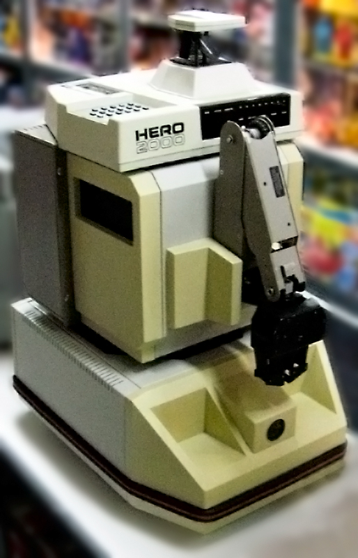
Heath’s catalogue adds that “eight are user definable”, and that next to the keypad sits “a seven-digit data display that shows addresses and their current data contents” (Heathkit catalogue, Spring–Summer 1986, p. 2). The specific meaning assigned to each of the other LEDs is a matter for the ET-19 manual and is left unclaimed here. What the sources establish is the count and the placement: sixteen indicators, head mounted, serving as a status readout. In keeping with the rest of the machine, this is display hardware the keypad/display 8042 slave and the user program can address to surface what the robot is doing.
8.7 Floppy-disk storage
The HERO 2000’s card cage can carry a floppy controller card, documented among the controller-card set in selectric.org’s firsthand restoration writeup, which gives the robot floppy-disk storage (selectric.org; cross-reference Vol. 3 for the full card set and the 12-slot passive backplane). This is the storage half of the host-development workflow: programs developed over the terminal port can be saved to and loaded from floppy, so work survives a power-down without re-keying.
The presence of a disk controller as a backplane card is itself part of the HERO 2000 story. The HERO 1 stored programs on cassette through its standard rear-panel port; the HERO Jr ran from a behaviour ROM and program cartridges. (The HERO 2000 has a cassette port too.) The HERO 2000 instead treats mass storage the way a desktop computer of its era did — a controller card on a bus, driving a floppy drive — which is consistent with its whole design as a card-cage computer on wheels rather than a fixed-function appliance. Heath’s catalogue sold the drive as the ETW-19-6, a “360K Disk Drive” at $399.95, first listed in Fall 1987 as “Available August” (Heathkit catalogue, Fall 1987). The controller card’s part number is not specified in the sources and is left unclaimed.
8.8 Programming the HERO 2000
8.8.1 HERO 2000 BASIC, resident in ROM
The HERO 2000 is programmed primarily in HERO 2000 BASIC, and the defining fact about that BASIC is where it lives: it is a full BASIC held in the 64 KB ROM, alongside the system monitor and the demo, diagnostic, and sensor-adjustment routines (HERO 2000 spec sheet; theoldrobots.com; Computer History Museum; cross-reference Vol. 3 for the ROM contents). The interpreter is always present — there is no cartridge to insert and no tape to load before a program can be written. Power the robot up and the language is there.
This is a real break from the earlier HEROs. The HERO Jr’s BASIC came on a program cartridge; the HERO 1’s BASIC was an accessory ROM needing a memory board and an RS-232 interface, and without it the robot was programmed from its keypad through an 8 KB monitor. Building a complete BASIC into ROM makes the HERO 2000 self-hosting: the robot is its own programming environment, and the language has direct, built-in access to the machine’s subsystems — the motors, the 360-degree sensor ring, the arm, and the direct text-to-speech subsystem (Vol. 7) — through its command set.
The keywords, statement syntax, and the I/O/robotics command set of HERO 2000 BASIC are documented in the ET-19 Programming Manual and are deferred to it entirely. This volume does not invent or paraphrase the language’s keywords; a reader writing programs should work from the factory manual.
8.8.2 Assembly and the host-development workflow
Beyond BASIC, the HERO 2000 can be programmed in assembly language for the 8088 (HERO 2000 spec sheet; programming notes). The natural workflow for assembly — and for serious BASIC development — is the host-development pattern the I/O layer is built to support: connect a terminal or host computer to the RS-232 terminal port, develop and edit there, run on the robot, send listings to the printer on the second port, and save the result to floppy. The 8088 master is the same processor family as the IBM PC/XT and the Heath/Zenith Z-151 (selectric.org), which made it a familiar target for anyone already working in that ecosystem.
The shape of this workflow is the clearest single expression of what separates the HERO 2000 from its siblings. It is designed to be developed against from a desk, with a terminal, a printer, and disk storage, in a high-level language that is always resident — the working pattern of a small computer, applied to a robot.
8.8.3 The Heath/Zenith Educational Systems course
The HERO 2000 was not just a product but a teaching platform. Heath/Zenith Educational Systems built courses around it: EE-1900, Intelligent Machines, and EE-1901, Electronics for Automation (each $99.95), whose experiments use a HERO 2000 equipped with its arm (Heathkit catalogue, Spring–Summer 1986, p. 3); and EB-1950, HERO 2000 Programming and Interfacing, from Fall 1987 (Heathkit catalogue, Fall 1987, p. 69). The Computer History Museum catalogs course material alongside the ET-19 manuals (Computer History Museum). The course material is the pedagogical companion to the Programming Manual: it taught programming and interfacing against the very I/O layer this volume describes — the serial ports, the sensor ring, the arm, and the BASIC in ROM — and it is part of why the HERO 2000 was positioned as an advanced educational and automation trainer rather than a consumer robot.
8.9 How the I/O story differs from the HERO 1 and HERO Jr
The communications and programming layer is where the HERO 2000’s generational distance from the earlier HEROs is most concrete. Three contrasts capture it.
Two serial ports, with standing roles, versus one optional channel. The HERO 1 offered a single serial link as an option (ET-18-10) and the HERO Jr reached RS-232 through an optional accessory (RTA-1-3); the HERO 2000 ships two DCE RS-232C ports — terminal/host and printer — to 38,400 baud as core hardware.
A host-development workflow with floppy storage, versus keypad/cartridge programming. The earlier machines were programmed at the robot — the HERO 1 from its keypad and monitor, the HERO Jr from one-touch personality keys and program cartridges. The HERO 2000 is programmed against from a terminal, with a printer and a floppy drive, the way a desktop computer is.
A full BASIC in ROM, versus a cartridge/expansion language. The HERO Jr’s BASIC arrived on a cartridge; the HERO 2000’s is permanently resident in the 64 KB ROM, always available the instant the robot powers up.
Table 1 — How the I/O story differs from the HERO 1 and HERO Jr
| HERO 1 (ET-18) | HERO Jr (RT-1) | HERO 2000 (ET-19) | |
|---|---|---|---|
| Serial ports | 1 RS-232 (optional ET-18-10) | 1 RS-232 (optional RTA-1-3) | 2 RS-232C (DCE): terminal + printer, to 38,400 baud |
| Wireless | RF remote (ET-18-35/-36/-37), ~100 ft | RF remote (RTA-1-2), 75 MHz | Wireless remote ~100 ft + two-way radio data link to console |
| Status display | Six-digit LED display on the head | Eight speech-synchronised LEDs | 16 head-mounted status LEDs |
| Mass storage | Cassette port (standard) | Behaviour ROM + program cartridges | Floppy controller card → floppy disk |
| Primary language | Keypad / monitor; assembly | Cartridge BASIC; HJPL | HERO 2000 BASIC in 64 KB ROM + 8088 assembly |
| Development model | At the robot (keypad) | At the robot (keys/cartridge) | Host development over the terminal port |
Sources differ on several HERO 2000 figures elsewhere in this deep dive — the 8088
clock, the slave-processor family, the speech chip, the battery rating — and those
conflicts are flagged in their home volumes. The I/O facts in this volume (two DCE
RS-232C ports, 38,400 baud, ~100-foot two-way radio link, 16 head LEDs, the floppy
controller, and BASIC in ROM) are drawn from the transcribed factory spec sheet
(hero.dsavage.net) and the supporting secondaries, and the authoritative primary
for the connector pinouts, the RF particulars, and the BASIC syntax remains the
factory ET-19 Technical and Programming Manuals, which a reader should consult
for the definitive detail.
Comments (0)