ET-3400 Microprocessor Trainer · Volume 3
Building the Kit
The ET-3400 was a kit in the full Heath sense: a bag of resistors, a stack of IC sockets, a bare circuit board printed on both sides, a small keyboard board, a support bracket, a transformer and a blue cabinet, and a manual that told the builder what to do with each, one checkbox at a time. It was not a hard kit. There are no coils to wind, no alignment, and almost every active part plugs into a socket after the soldering is done. But it was a long one, with several hundred solder joints on a board whose foils run close together, and it ends with a set of tests that make the builder prove each part of the computer before trusting it. This volume follows the manual’s structure, describes the steps that mattered, and ends with what is known about kits built and unbuilt.
3.1 The manual
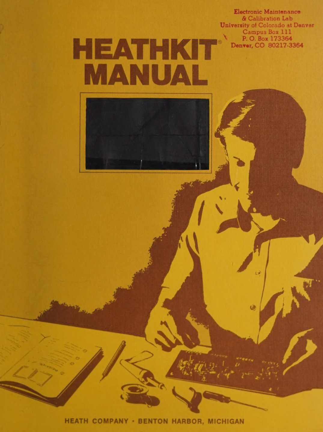
The assembly manual, Heath part 595-2021, runs to 120 pages in the 1977 printing (-03) examined here, with a separate Illustration Booklet for the large Pictorials and the fold-out schematic. Its table of contents gives the order of work (manual, p. 2):
Table 1 — The assembly manual, Heath part 595-2021, runs to 120 pages in the 1977 printing (-03) examined here, with a separate Illustration Booklet for the large Pictorials and the fold-out schematic. Its table of contents gives the order of work ([manual, p. 2](https://archive.org/details/manualsplus11737))
| Section | Page |
|---|---|
| Introduction | 3 |
| Assembly Notes (tools, soldering) | 4 |
| Parts List | 7 |
| Step-by-Step Assembly: main circuit board | 10 |
| keyboard circuit board | 24 |
| support bracket assembly | 27 |
| cabinet assembly and wiring | 30 |
| Initial Tests: voltage tests, tests continued, operational tests | 34–41 |
| Final Assembly | 42 |
| Operation (keyboard, entering programs, breakpoints, sample programs, monitor listing, memory map, instruction set) | 45–90 |
| In Case of Difficulty and Troubleshooting Charts | 91–106 |
| Specifications, Theory of Operation, Semiconductor Identification | 107–113 |
More than half the book is not about assembly. From page 45 on it is a programming manual for the finished machine: the monitor’s commands, seven sample programs, the complete monitor listing with flowcharts, the memory map and Motorola’s instruction-set summary. Volumes 4 and 5 use that half.
The later printing, 595-2021-06, has the same 1977 copyright date on its title page but a black-and-white cover, the illustration booklet bound in, a “Heath Parts Price List” dated 10/20/80, and a back cover reading “Heath Zenith”, so it was printed after Zenith bought Heath in 1979 (595-2021-06).
3.2 Tools and parts
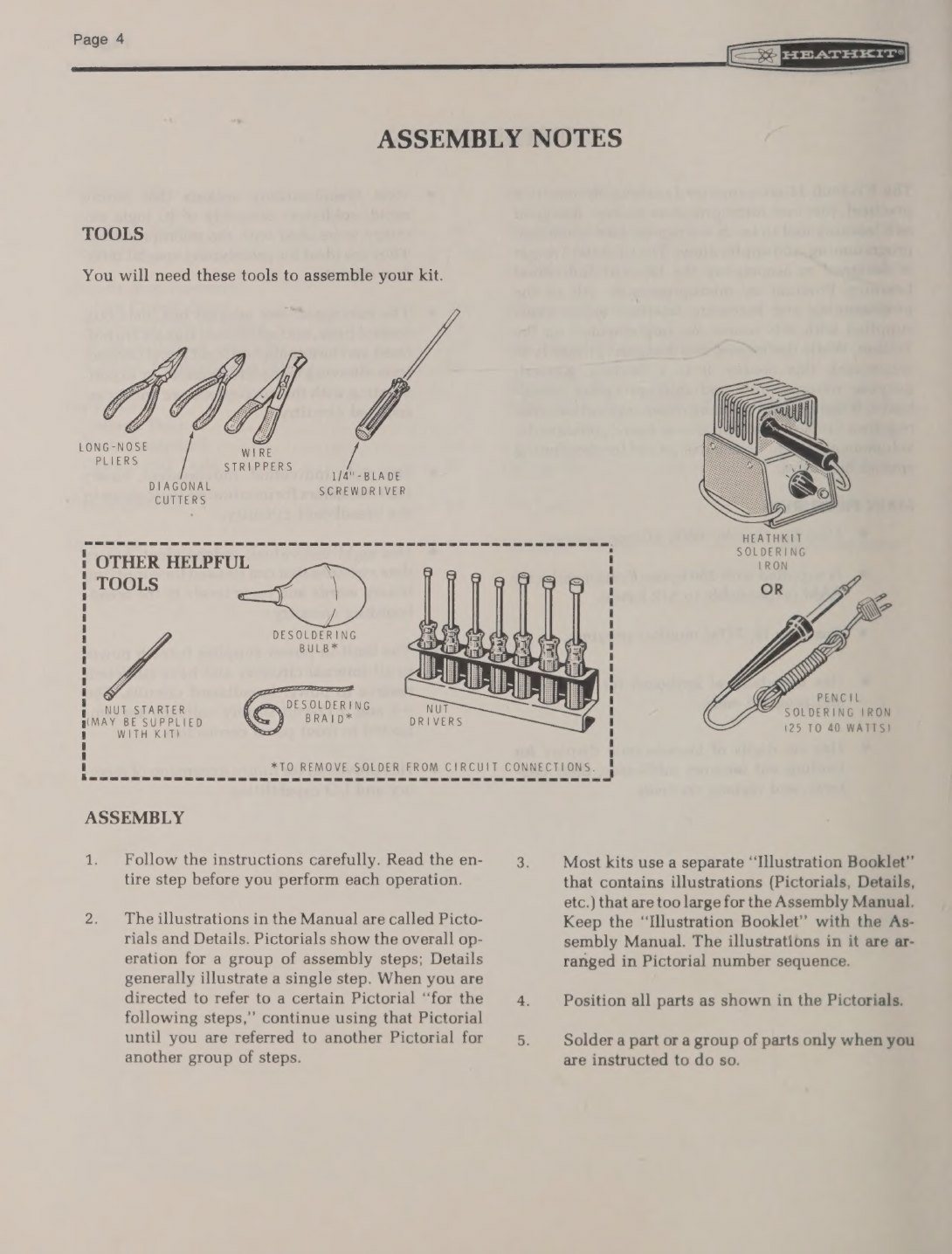
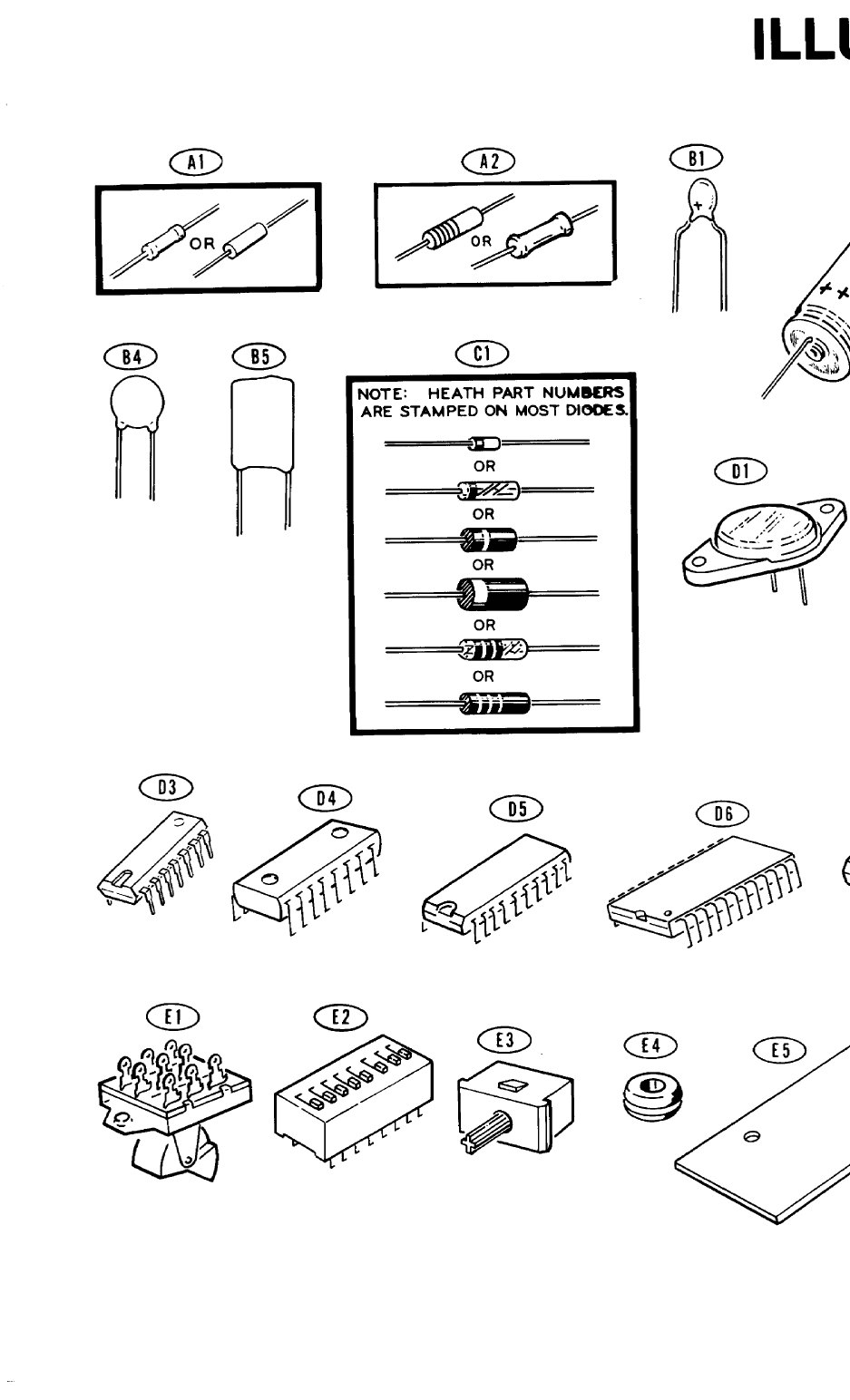
The tools are the standard Heath list: long-nose pliers, diagonal cutters, wire strippers, a small screwdriver, and a “25 to 40-watt pencil soldering iron with a 1/8” or 3/16” chisel or pyramid tip”, with a desoldering bulb or braid and nut drivers as extras (manual, pp. 4–5). The parts list groups the components by type and gives each a Heath part number and a circuit number, the number the builder would quote to Heath’s Replacement Parts department if anything went missing.
3.3 Step by step: the main circuit board
Assembly begins with the main board, which is also the front panel: the component side is screen-printed with the function labels, IC outlines and keypad outline that the user sees through the cabinet opening. The first step installs and solders a single resistor, R49 (1200 Ω), with the method spelled out in drawings: push the iron “against both the lead and the circuit board foil”, heat “for two or three seconds”, then feed in solder and let it flow round the connection (manual, p. 10). The next page shows a good joint, two bad ones, and a solder bridge, with the warning that a bridge can be made by touching an adjacent joint, by using too much solder, or by dragging the iron across other foils.
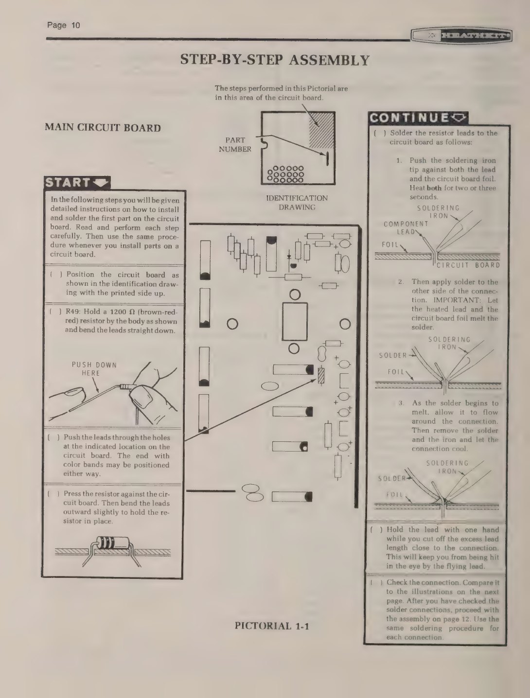
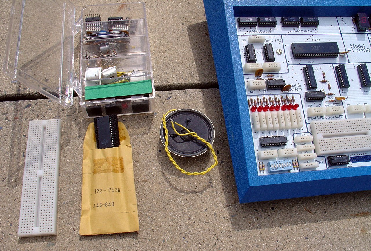
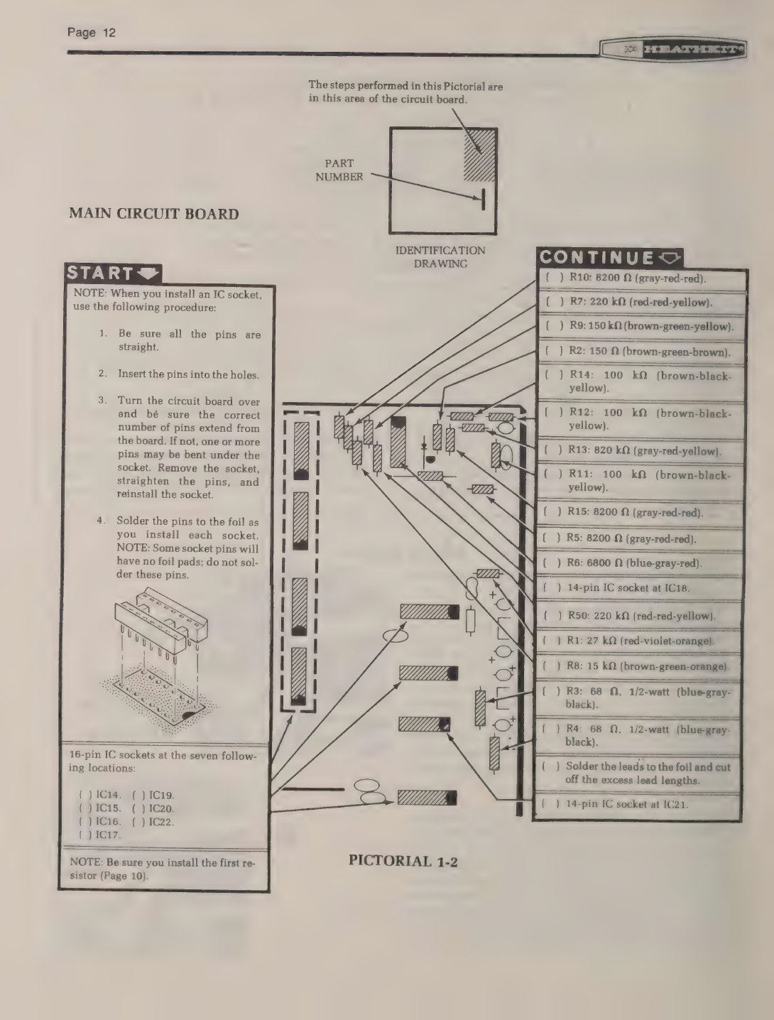
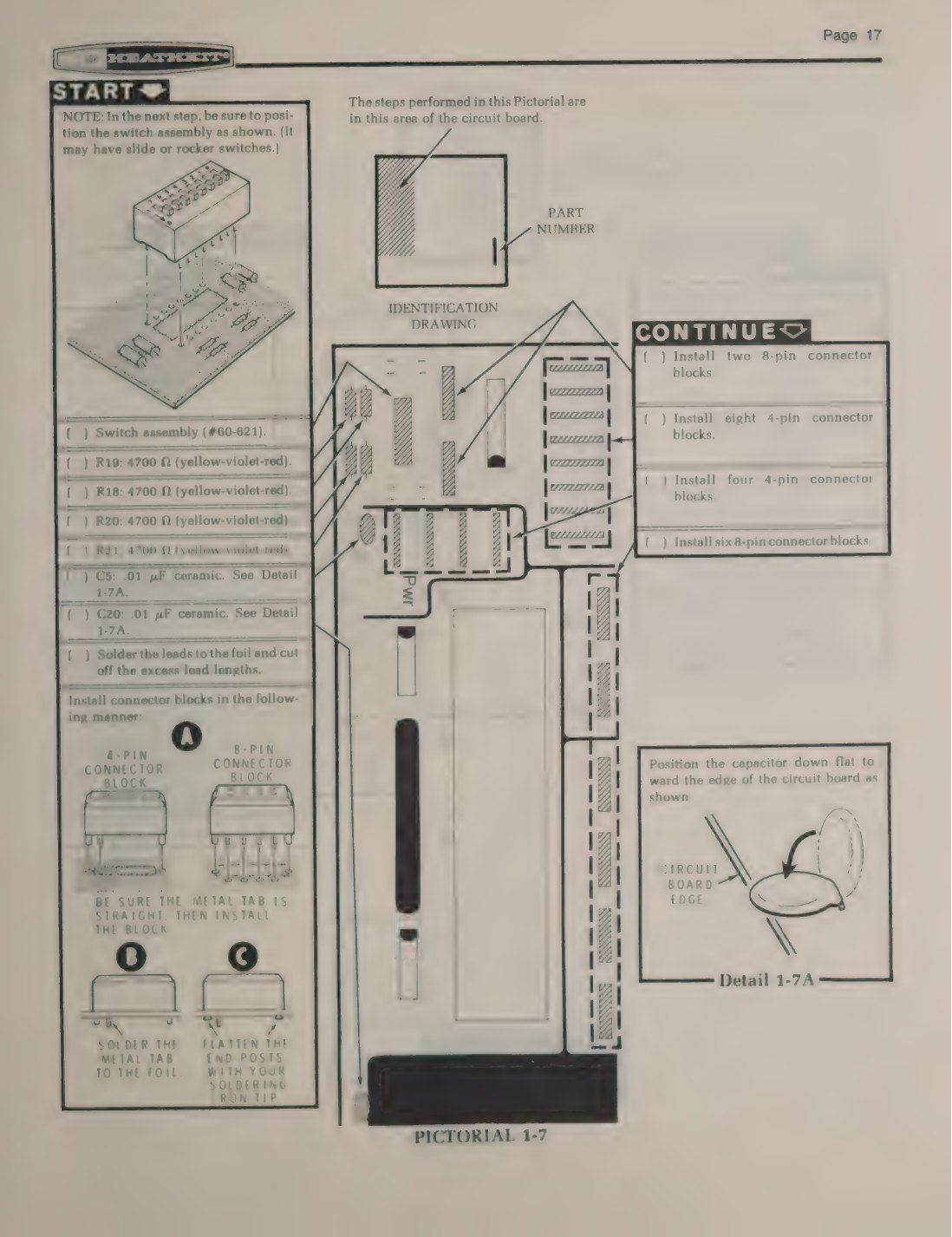
The board is then built area by area. Each page shows the whole board as a small outline with the area being worked on shaded, and a large Pictorial of that area with every part numbered. A “START” box and a “CONTINUE” box mark the page’s sequence. The work is resistors, small capacitors, diodes, the IC sockets, the terminal blocks along the bottom, the breadboard sockets, the eight logic LEDs and the DIP switch.
Sockets are the key to the build. Every IC goes into a socket, and none is installed until the board, keyboard and power wiring have been finished and the supply voltages checked. That protects the expensive MOS parts (the processor, the ROM and the RAMs) from soldering heat, from static during most of the assembly, and from a wiring mistake in the supply.
3.4 The keyboard board
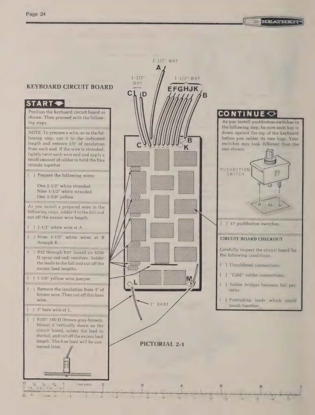
The keyboard is a separate small board. The builder prepares eleven short wires, installs six 8200 Ω resistors (R52 to R57) and a jumper, and then the 17 pushbutton switches, with the reminder to make sure “each key is down against the top of the keyboard before you solder its two lugs”, so that the keys line up when the boards are joined. A “Circuit Board Checkout” follows: look for unsoldered connections, cold joints and solder bridges (manual, p. 24). The keyboard board mounts under the main board, with its keys coming up through holes in it.
3.5 The support bracket and the power wiring
The power supply’s heavy parts hang on a metal support bracket under the board. The builder mounts a terminal strip and solder lugs, wires the two 1200 µF filter capacitors for the ±12 V supply, and then fits the five-volt regulator, IC31, a µA309K in a TO-3 can. The instruction is to “apply a liberal coating of the grease to the bottom” of the regulator from the supplied silicone grease, seat it in a TO-3 socket on the underside of the bracket, and screw it down: the bracket is its heat sink. The 6000 µF main filter capacitor C1 is held to the bracket with a cable tie, and a short length of flat braid, soldered to a pad on the board, grounds the bracket (manual, pp. 27–29).
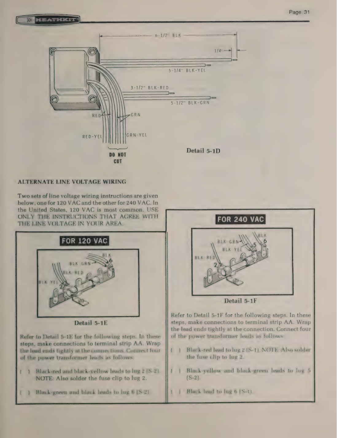
Cabinet assembly then installs the power transformer, whose primary leads are wired one way for 120 V and another for 240 V, the line cord (with a knot tied in it inside the cabinet as a strain relief), the fuse holder, and the power switch. The fuse label is filled in by hand: “3/8-Amp, 3AG, slow-blow” (manual, p. 33).
3.6 Initial tests
Testing comes in three stages, and the order is deliberate.
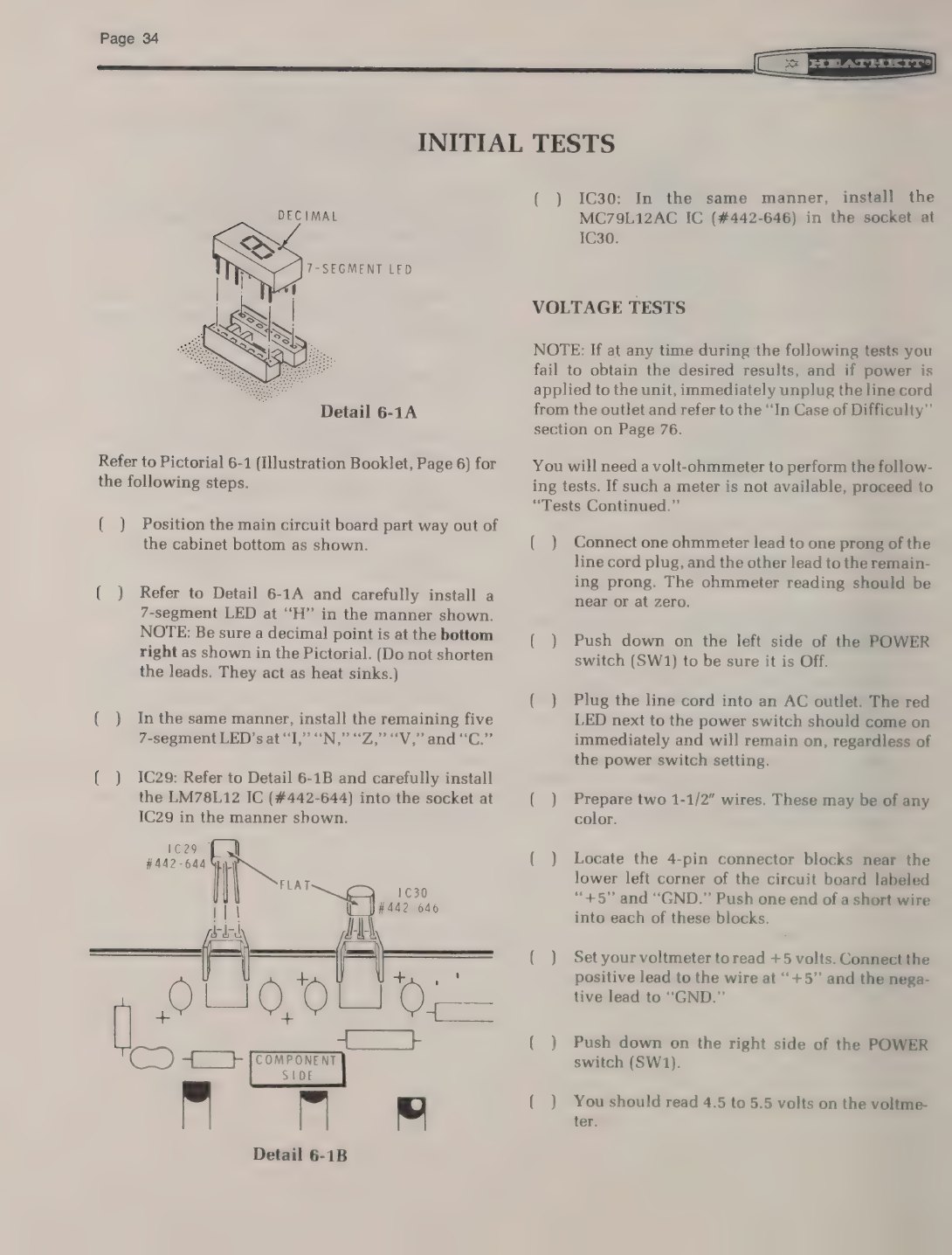
Voltage tests. With only the displays and the two small regulators installed, the builder checks the line cord with an ohmmeter, plugs in, and confirms that the red pilot LED beside the power switch lights “immediately and will remain on, regardless of the power switch setting”. Then, with two short test wires pushed into the panel’s connector blocks, the meter should read 4.5 to 5.5 volts at +5 and 10.8 to 13.2 volts at +12 and at −12. A builder without a meter could skip to the next stage (manual, p. 34).
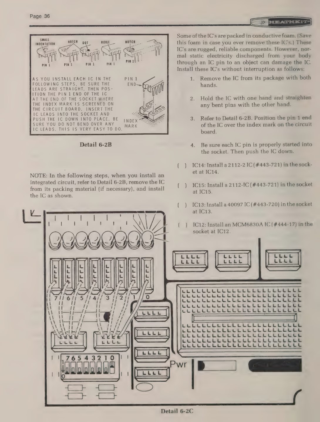
Tests continued. Shorting the SEGMENT TEST pins should light all seven segments and the decimal point of every digit. The builder then presses the 17 square knobs onto the pushbuttons, sticks a lettered or numbered label onto each, and covers each display with a red filter label (“You should have two labels left over”). Only now are the integrated circuits installed, with a page of instructions on static: they are “rugged, reliable components”, but “static electricity discharged from your body … can damage the IC”, so each is to be taken from its package with both hands, its pins straightened, and pressed into its socket “without interruption”. The 2112 RAMs, the 40097 keyboard buffer, the MCM6830A ROM and, last, the MC6800 processor go in one after another (manual, pp. 35–37).
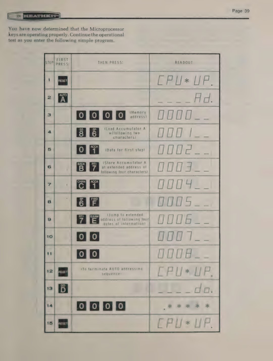
Operational tests. With every IC in place, the builder plugs in, turns on, and presses RESET; the display should read CPU UP. A chart then walks through every key, with the display each should produce, so that a dead key or a bad column shows at once. Next the builder enters a short program from the keypad (load accumulator A with 01, store it at extended address C16F, jump), runs it, and sees the decimal point of the H display light. The manual explains why: “the ‘6’ addressed the LED and the ‘F’ addressed the decimal point”, and by changing the last byte the builder can light each segment of each digit in turn (manual, pp. 37–41). It is the first program most owners ever ran on the machine, and it teaches the display addressing of volume 2 before the course has said a word about it.
The same pages offer the 40-pin expansion connector as an option: buy a connector with “.025” square pins on .100” centers”, fit it between IC2 and IC3, and wire eight jumpers to the data lines. “If you do not wish to install a connector at this time, proceed directly to ‘Final Assembly’” (manual, p. 41).
3.7 Final assembly
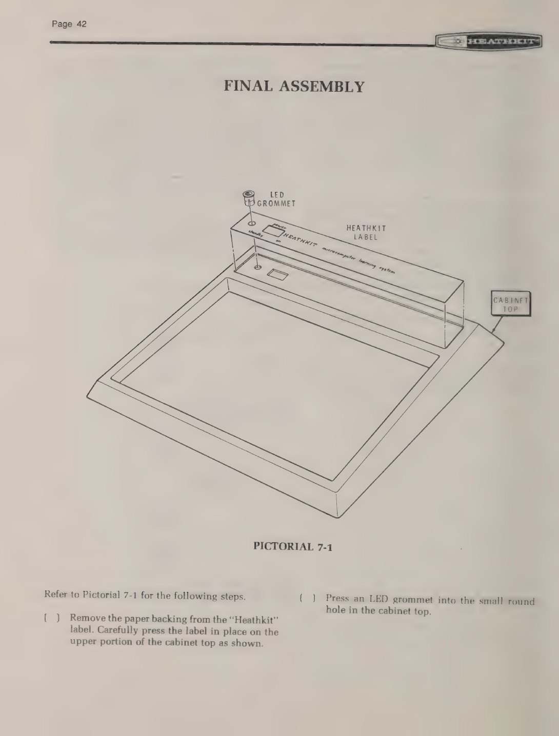
Final assembly is short: the “Heathkit” nameplate and the LED grommet go on, the board is fastened into the cabinet bottom, the cabinet top is fitted with hex-head screws, and the blue-and-white identification label (model and series number) and four feet are stuck to the bottom (manual, pp. 42–44).
3.8 What an ET-3400A kit contained
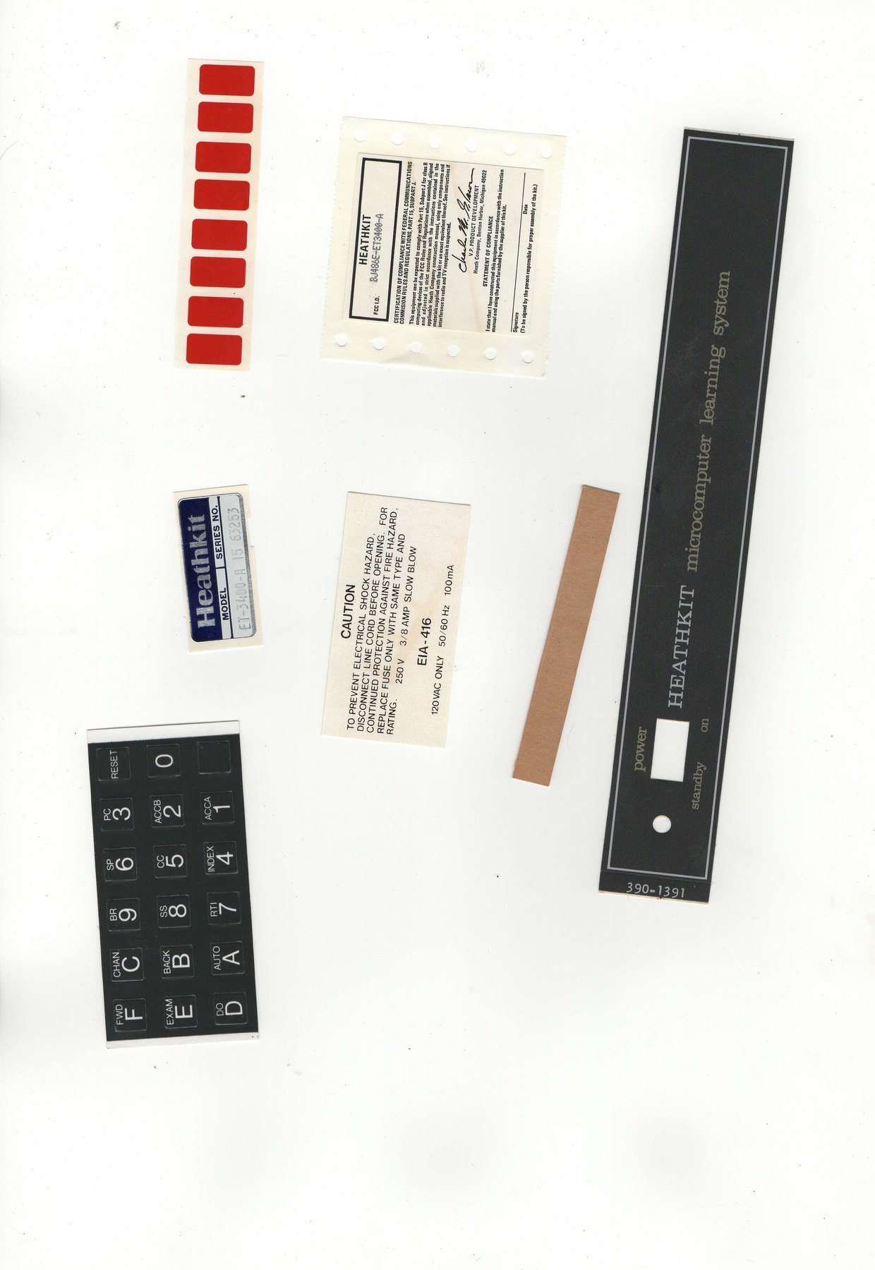
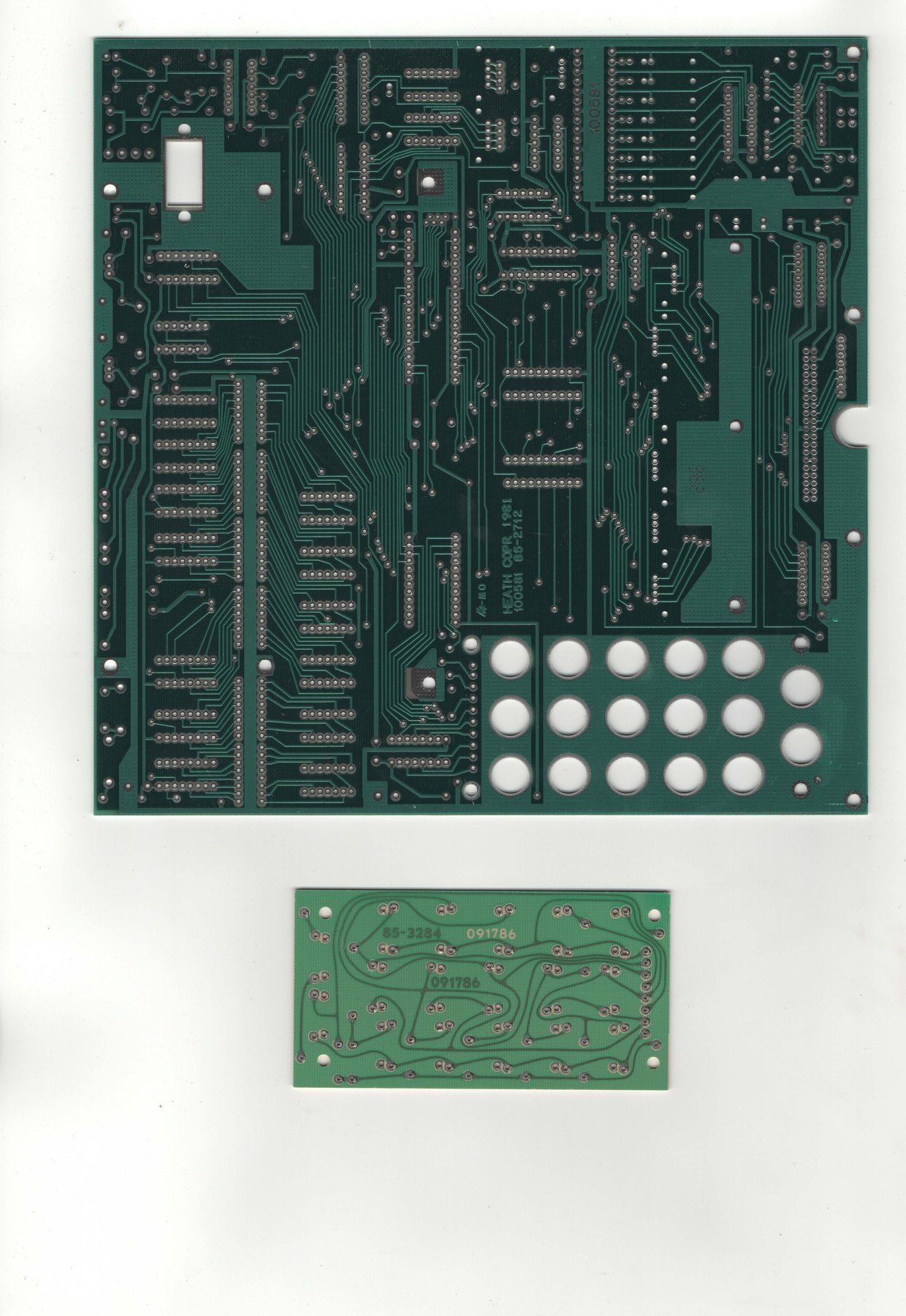
One unbuilt ET-3400A kit has been scanned in part. Its two circuit boards, bare, show the main board’s component side with the blue screen-printed panel and the keyboard board beside it, and the solder side in green resist. The same scan set includes the paper inserts that came in the box: the parts order form and envelope, the warranty, and a sheet of labels with the dark nameplate strip, the keypad legends, the red display filters and the pilot-lamp label (Internet Archive, et3400-a scans). The ET-3400A’s assembly manual has not been found, so the A kit’s step order and any changes to the tests are not documented here.
3.9 How long it took
No Heath figure for the ET-3400’s assembly time was found; the catalogues give “about 10 hours” for the ETA-3400 accessory but no figure for the trainer (Fall 1987, p. 64). The manual’s own warning about workmanship is the best guide to where the time went: in its trouble-shooting section Heath says that “about 90 percent of the kits that are returned to the Heath Company for repair do not function properly due to poor connections and soldering” (manual, p. 91). A trainer that powered up to CPU UP at the first attempt had been soldered carefully.
Sources
- Heath Company. Heathkit Manual for the Microprocessor Trainer, Model ET-3400, 595-2021-03, © 1977. Internet Archive (DLARC). https://archive.org/details/manualsplus_11737
- Heath Company. Same, 595-2021-06 (c. 1980), with Illustration Booklet. https://archive.org/details/HeathkitManualForTheEt-3400MicroprocessorTrainer
- Internet Archive, “et3400-a scans” (bare ET-3400A boards and kit inserts). https://archive.org/details/et3400-a-scans
- Heathkit catalogue, Fall 1987. World Radio History. https://www.worldradiohistory.com/Archive-Catalogs/Heathkit-Catalogs/Heathkit-1987-Fall.pdf
- DigiBarn Computer Museum. https://www.digibarn.com/collections/systems/heathkit-microprocessor-learning-kit/
Comments (0)