ET-3400 Microprocessor Trainer · Volume 6
Restoration and Common Faults
An ET-3400 that has spent forty years in a school store-room or a garage usually fails in a few predictable ways, and almost none of them is the processor. The trainer’s design helps: every IC is in a socket, the supplies are simple, and the manual’s trouble-shooting section was written for a builder with a voltmeter and some wire. This volume sets out safety first, then a safe first power-up, the faults that owners have reported, the manual’s own fault-finding method, the parts that are hard to replace, and the modern additions that people now build for the trainer.
6.1 Safety
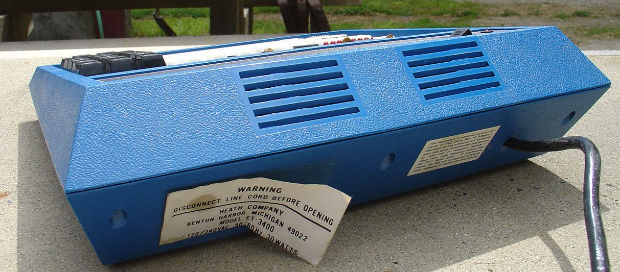
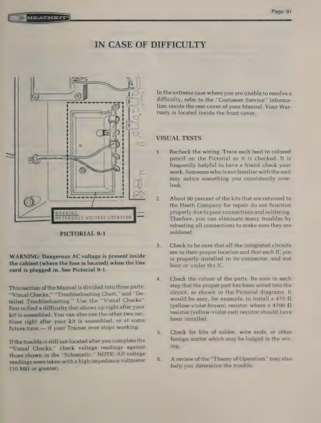
The trainer is a low-voltage device everywhere the user normally touches it, but not inside. The manual’s trouble-shooting section opens with a warning: “Dangerous AC voltage is present inside the cabinet (where the fuse is located) when the line cord is plugged in”, with Pictorial 9-1 marking the “hazardous voltage location” (ET-3400 manual, 595-2021-03, p. 91). The fuse, the power switch and the transformer primary are all at mains potential, and the pilot LED is lit whenever the cord is plugged in, whatever the switch says, because the transformer is always energised in Standby.
- Unplug the trainer before opening it, not merely switch it off.
- Fit only the specified fuse: 3/8 A, 3AG, slow-blow (manual, p. 33).
- Inspect the line cord. The 1977 voltage test checks continuity “between one prong of the line cord plug” and “the remaining prong”, which indicates a two-wire cord on the original kit; an old two-wire cord with cracked insulation should be replaced, and a three-wire cord with the cabinet and transformer frame grounded is a reasonable modern improvement.
- Check how the transformer primary is wired. The kit could be wired for 120 V or 240 V, with two different connections at terminal strip AA (manual, p. 31); a trainer from another country may be wired for the other voltage.
- Use the manual’s precautions when probing: “Do not remove an IC while the line cord is plugged in”, and do not let a probe short a supply point to ground (manual, p. 92).
6.2 A safe first power-up
The order below follows the manual’s own initial tests, with the cautions that old electrolytic capacitors call for.
- Look before applying power. Open the cabinet, check for corrosion, broken wires, swollen or leaking capacitors, and loose ICs. Note which ICs are fitted; many trainers have had chips borrowed or swapped.
- Remove the MOS parts. Taking out the processor (IC11), the ROM (IC12) and the RAMs (IC14 to IC17) before the first power-up protects the irreplaceable ROM from a supply fault. The manual installs them last for the same reason (manual, p. 36).
- Bring the supply up slowly. The main filter capacitor C1 is a 6000 µF electrolytic, and the ±12 V supply has two 1200 µF capacitors (manual, pp. 27–28). A variable transformer, or a series lamp limiter, lets the capacitors re-form and shows up a short before it does damage.
- Measure the supplies. The manual’s tolerances are 4.5 to 5.5 V at +5 and 10.8 to 13.2 V at +12 and −12, measured at the panel’s connector blocks (manual, p. 34). Herb Johnson recorded −12.4, +12.2 and +4.9 V on a working ET-3400A (retrotechnology.com). Check the +5 V rail for ripple with an oscilloscope if one is available.
- Short the SEGMENT TEST pins. Every segment and decimal point should light, with no processor involved.
- Refit the ICs and press RESET. The display should show CPU UP. Then work through the key-by-key chart of the operational tests and enter the three-instruction display program from volume 3.
6.3 Faults owners report
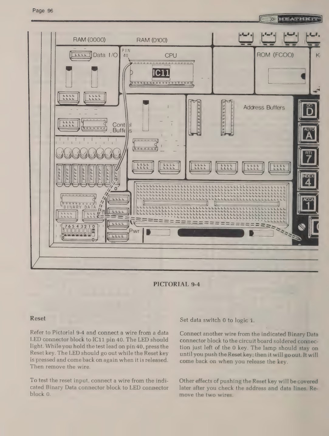
Corroded pins and bad sockets. The most consistent report from restorers is not a dead chip but a bad contact. When Lee Hart bought an ET-3400 in February 2024 it arrived “somewhat dirty, with three ICs whose pins had rotted off”; the clock, reset, displays and buses were active but the keyboard was ignored, and the faults included bad sockets and corroded IC pins as well as a suspect ROM. Replacing the 6800 and the RAM “alone did not fix it” (Herb Johnson, retrotechnology.com). Cleaning sockets with contact cleaner and gently cleaning the pins is the first job on any trainer that misbehaves.
Flickering CPU UP and spontaneous resets. On the Southeast Heathkit Computer users’ mailing list in 2007, Peter Nelson described an ET-3400A that, after months unused, showed a flickering “CPU UP” and “seemed to be resetting itself 100 times/second”; tapping it steadied it, but it still reset every ten minutes and lost the program. “Removing and re-seating all the chips solved the problem” (sebhc list, 27 February 2007).
RAM. Paul Pennington, on the same list, traced a non-starting ET-3400A to “the two 2114 memory chips”. He cleaned the oxidised sockets and pins, but the cure was replacing the memory: the original chips, rated 250 ns, did not work, and 450 ns parts did. He was not sure why, and noted that the same chips had worked in a standard ET-3400, which runs at a slower clock (sebhc list, 26 February 2007). The original ET-3400 uses 2112 (256 × 4) static RAMs, two per 256-byte bank; the A model’s two 2114s are 1024 × 4 parts. Identify the chips on the board before ordering replacements.
All eights. A dirty board can show only eights on the display. The manual lists “all eights” among the symptoms of a crashed program as well (manual, p. 51), so a trainer that shows eights at switch-on may simply need RESET pressed, and one that shows them after RESET has a hardware fault.
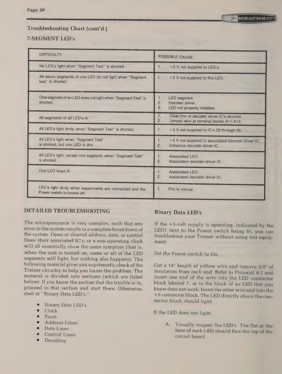
Display segments. The trouble-shooting chart ties each display symptom to its cause: no segments lit on SEGMENT TEST means no +5 V to the LEDs; one dark digit, its own supply or its LED; one dark segment, the LED, its latch driver (IC23 to IC28) or a badly seated LED; one LED that stays lit, the LED or its driver. Because the six latch drivers are identical, the manual suggests swapping a suspect one with its neighbour to see whether the fault moves (manual, pp. 92 and 94). And “LED’s light dimly when experiments are connected and the Power switch is turned off. This is normal” (manual, p. 94).
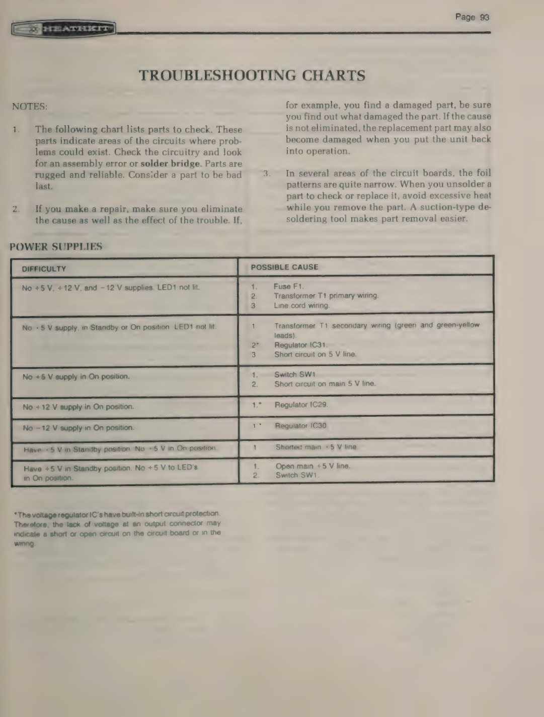
The five-volt regulator. IC31, a µA309K in a TO-3 can, supplies the whole logic load from a heat sink that is the support bracket, with silicone grease between them (manual, p. 27). Dried grease or a loose mounting makes it run hot. The chart’s first suspects for “No +5 V supply” are the transformer secondary wiring, IC31 and a short on the 5 V line (manual, p. 93).
6.4 The manual’s fault-finding method
Heath assumed a builder without test equipment beyond a voltmeter, and turned the trainer into its own logic probe. The detailed trouble-shooting begins: “The microprocessor is very complex, such that any error in the system results in a complete breakdown of the system. Open or shorted address, data, or control lines; their associated IC’s; or a non-operating clock will all essentially show the same symptom (that is, when the unit is turned on, some or all of the LED segments will light, but nothing else happens)” (manual, p. 94).
The method uses short lengths of yellow wire and the eight logic LEDs:
- The LEDs first. A wire from +5 V to each LED input proves the LEDs and their buffer, IC1. With IC1 removed, touching its socket’s output holes proves each LED alone.
- The clock. “The simplest test to determine if the clock (IC19) is operating is to place a portable radio near the clock and tune the radio across the broadcast band. If the clock is operating, you will hear several ‘beat’ signals.” The same check with a logic LED: wired to each of the clock’s four outputs, the LED should glow “noticeably dimmer than the same LED connected to +5 volts”, because of the clock’s 50 per cent duty cycle (manual, p. 95).
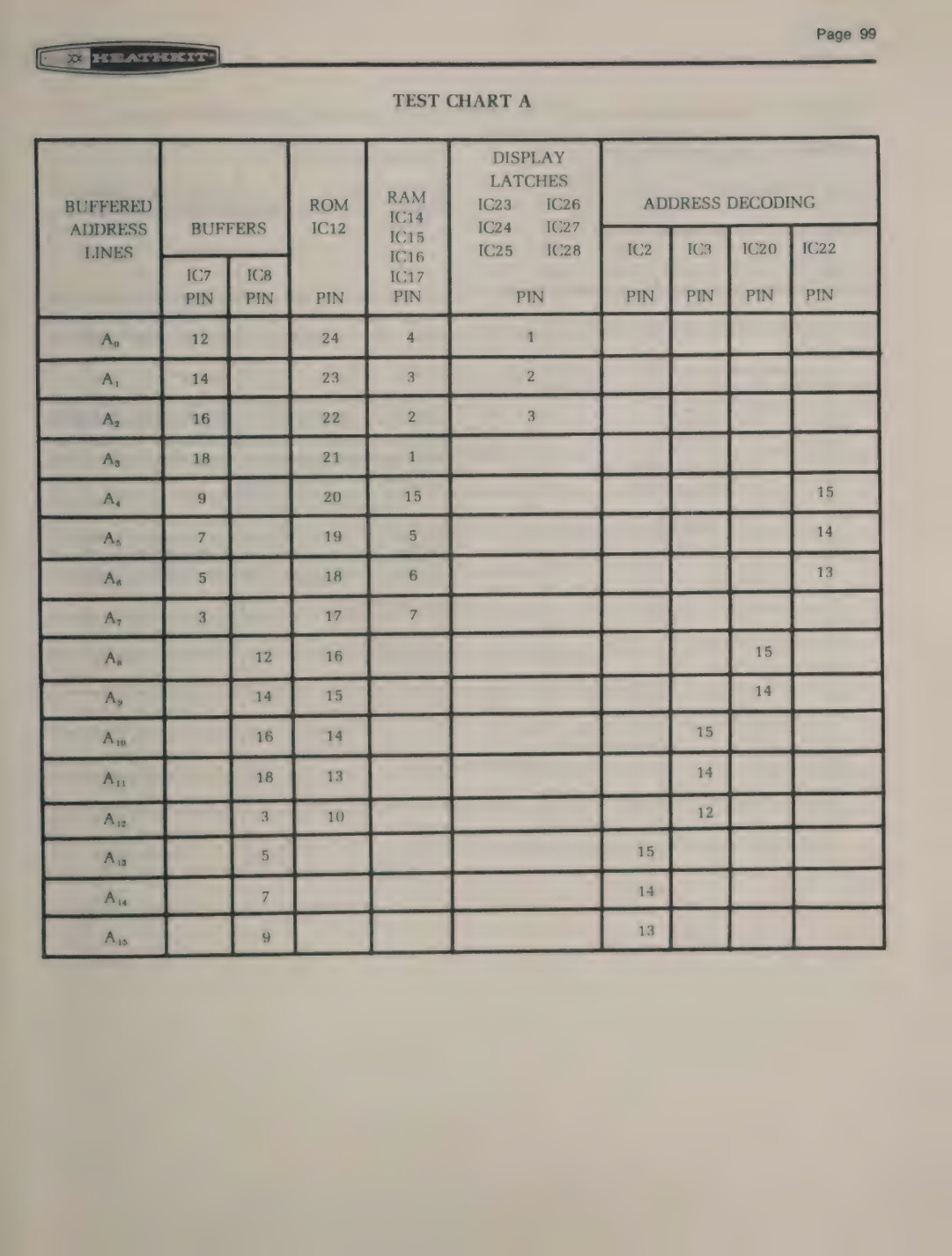
- Address, data and control lines. With the processor removed, jumper wires and the data switches drive each line in turn, and the LEDs, wired to the far end of the line through test charts A, B and C, show whether the line reaches every IC that should see it. The charts list, for every address line, the pin at each buffer, RAM, ROM and decoder (manual, pp. 96–106).
A logic probe and an oscilloscope make all of this quicker, but the method still teaches the machine, and it needs nothing that the trainer does not already have.
6.5 Parts that are hard to find
Table 1 — Parts that are hard to find
| Part | Problem | Approach |
|---|---|---|
| MCM6830A monitor ROM (IC12) | a Motorola mask ROM made for Heath (“must be mask programmed from the listing in this Manual”) | the listing in the manual is complete source; dumps of the ROM are held by collectors; Herb Johnson suggests a 2716 or 2732 EPROM “with an adapter” as a replacement (retrotechnology.com) |
| 2112 RAMs (ET-3400), 2114 RAMs (ET-3400A) | out of production for decades | new-old stock; confirm the type and pinout on the board; an A-model owner found access time mattered (above) |
| MC6800 and MC6875 | out of production | widely available as used or new-old-stock parts; the 6800 family’s later members are not drop-in replacements for the MC6800 and its clock chip |
| TIL312 displays | out of production | common-anode seven-segment LEDs of the same footprint; compare the pinout in the manual’s identification chart |
| keypad switches, labels | wear | the switches are standard pushbuttons on a separate board; the legends are stick-on labels |
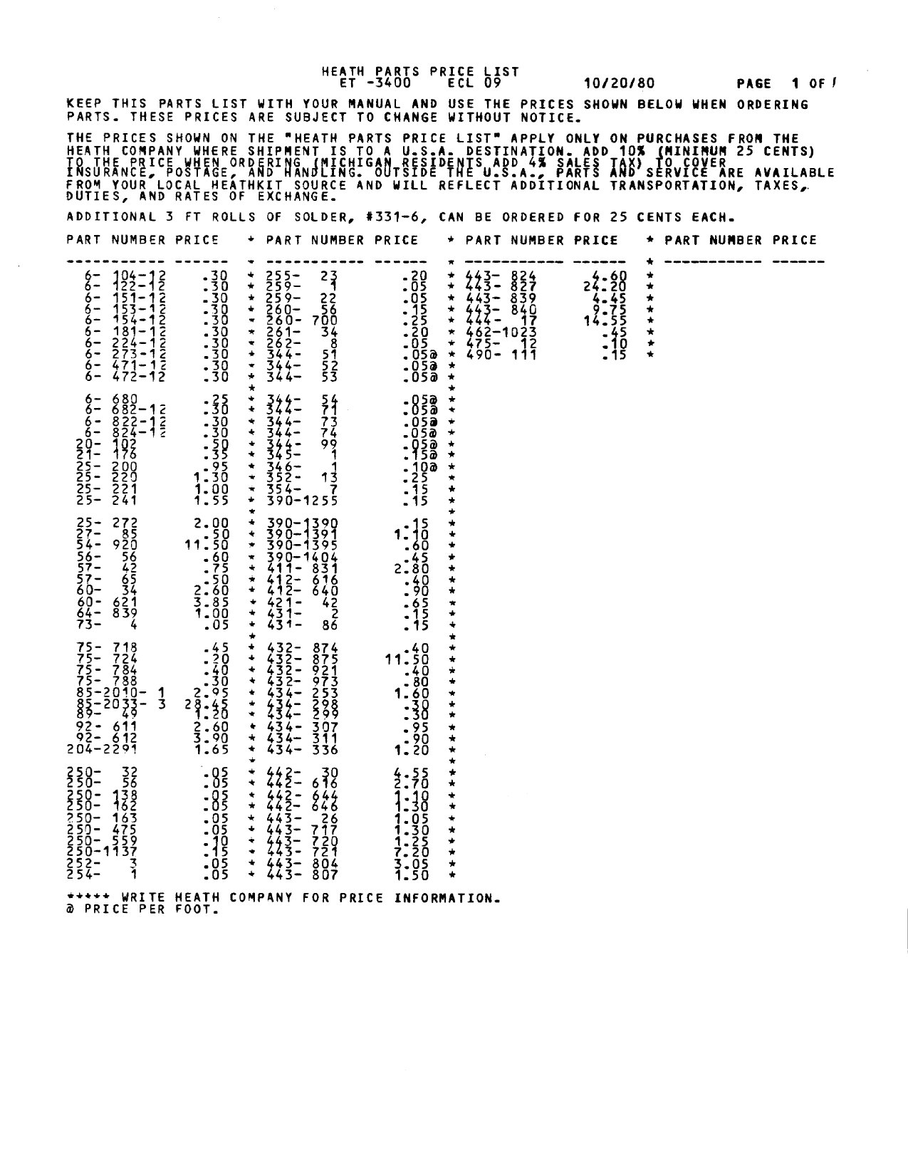
The later printing of the manual includes a “Heath Parts Price List” for the ET-3400, dated 10/20/80, which lists Heath part numbers and their prices at that date; with the parts list and the identification charts it is the way to translate a Heath number on a bag or a chip into a standard part (595-2021-06).
6.6 Period and modern modifications
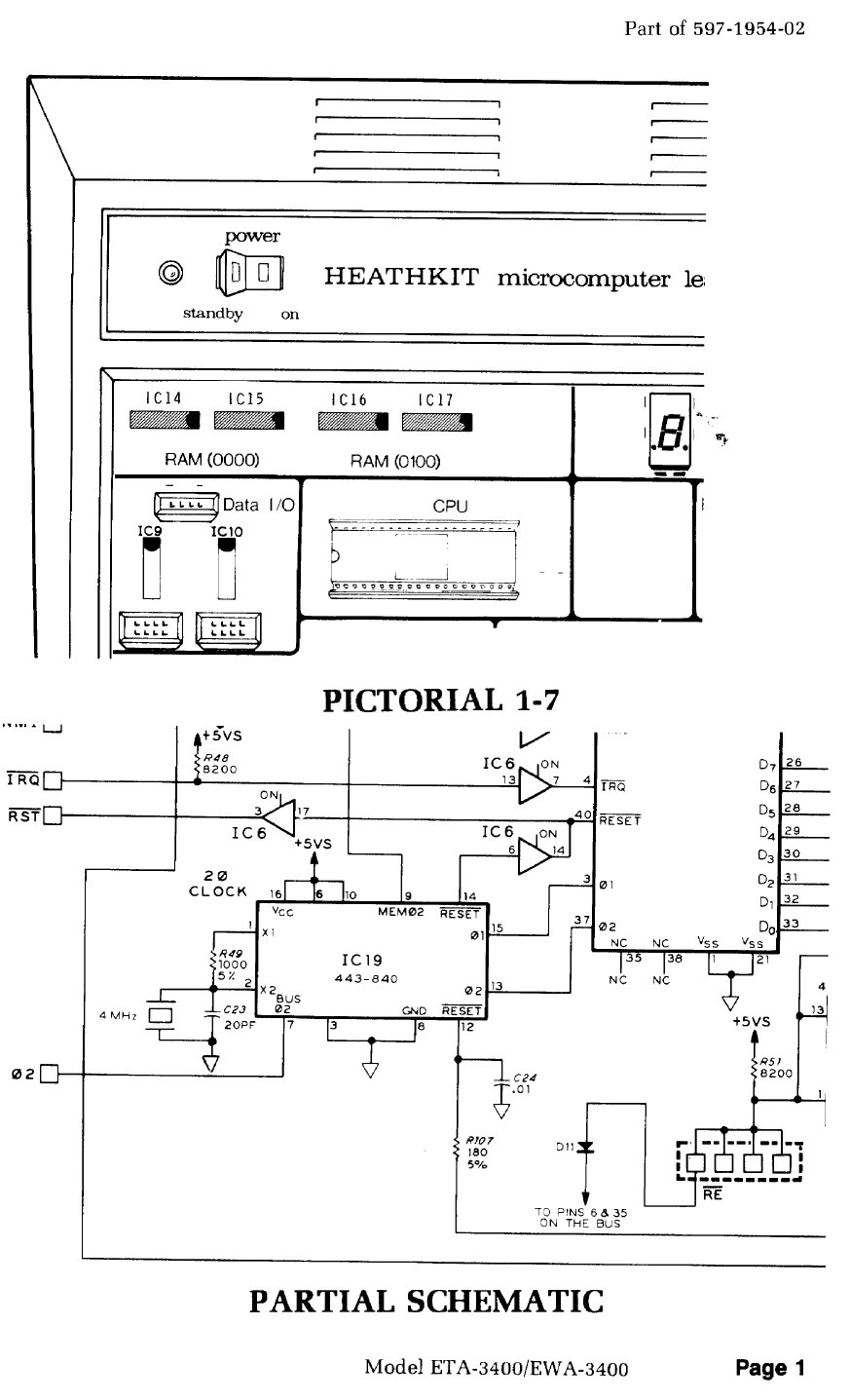
The ETA-3400 modification. Fitting the ETA-3400 accessory meant modifying the trainer: the clock was changed to run at 1 MHz and the expansion connector was wired. Lee Hart’s trainer has been modified this way, with a 4 MHz crystal on the MC6875 (retrotechnology.com). A trainer with an unexpected crystal near IC19, or with the 40-pin connector fitted, has probably had this done; it will run the course’s timing experiments twice as fast. The modification pages bound into the 595-2021-06 manual show the clock section and the extra wiring; Scott Baker notes that Heath’s “ET-3400-A modification instructions for adding the expansion header” also call for EMI/RFI shielding of the trainer (Scott Baker, 2020).
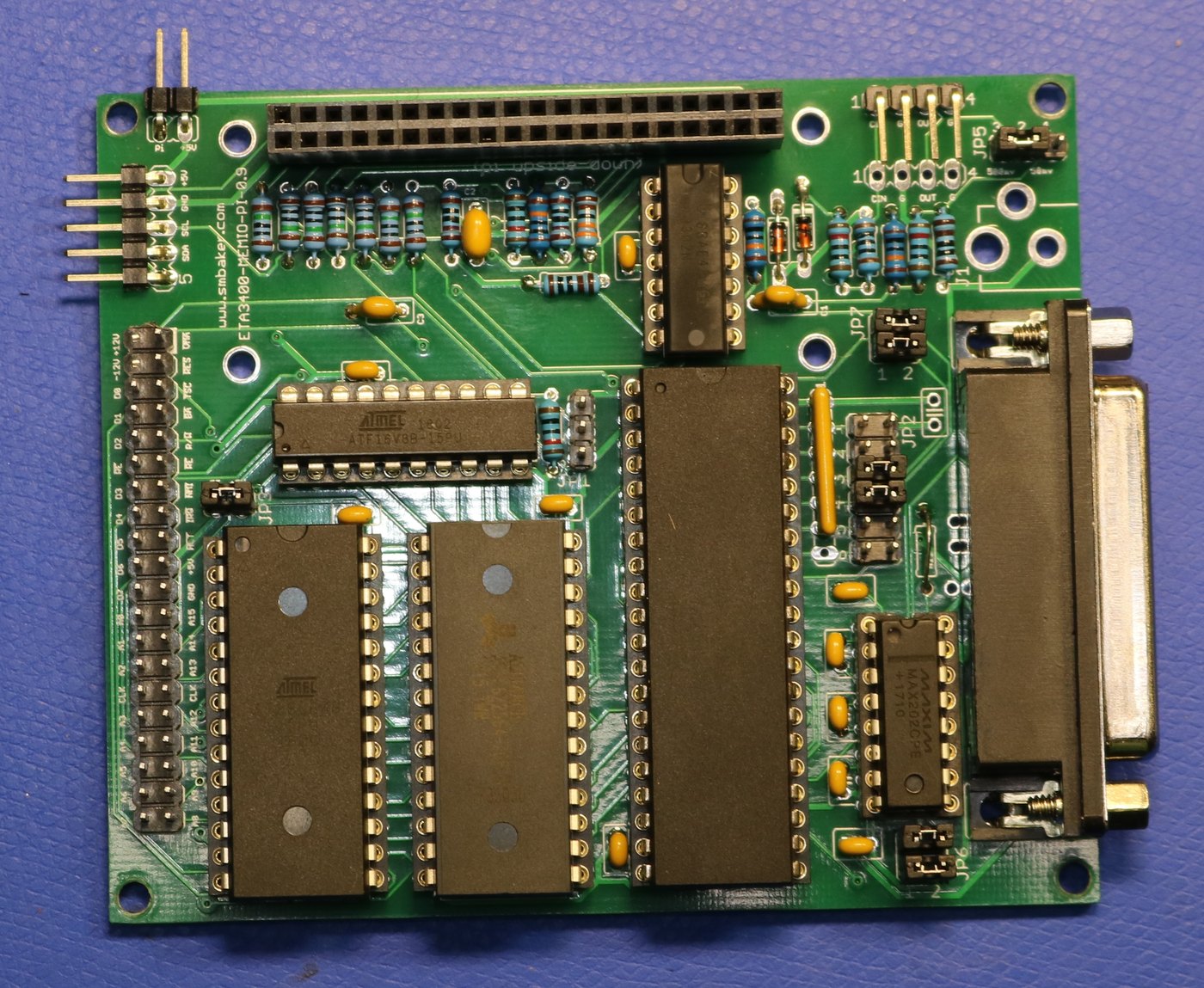
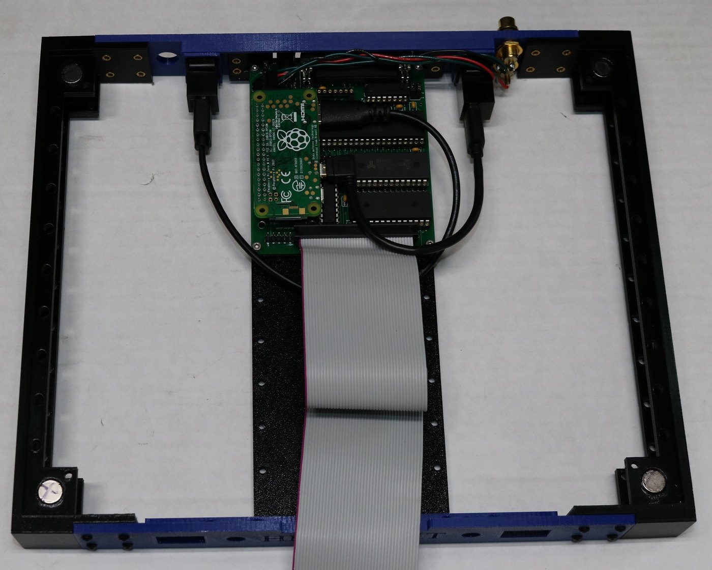
A modern ETA-3400. In 2020 Scott Baker designed a replacement memory and I/O board for the trainer, also called ETA-3400: one 32K static RAM, a 28C64 EEPROM in place of the original pair of ROMs, a 6821 PIA driving an RS-232 port and a cassette interface, an ATF16V8 programmable logic device for address decoding, and an optional Raspberry Pi Zero W on a header so that the trainer can be reached over the network. It connects by the same 40-pin ribbon cable and fits a 3D-printed case under the trainer (Scott Baker, “ETA-3400 memory/IO expansion”, 2020).
Emulation. The 6800 and the trainer’s simple hardware are easy to emulate, which makes it possible to try programs before keying them in. This dive’s own emulator, described in volume 5, reproduces the display and keypad and runs the manual’s sample programs.
Sources
- Heath Company. Heathkit Manual for the Microprocessor Trainer, Model ET-3400, 595-2021-03, © 1977: In Case of Difficulty and Troubleshooting Charts (pp. 91–106). https://archive.org/details/manualsplus_11737 ; 595-2021-06 with parts price list and ETA-3400 modification pages: https://archive.org/details/HeathkitManualForTheEt-3400MicroprocessorTrainer
- Johnson, Herb. “Heathkit ET-3400A 6800.” retrotechnology.com, revised April 2024. https://www.retrotechnology.com/restore/et3400A.html
- Southeast Heathkit Computer users’ mailing list (sebhc), “ET-3400A Repaired”, February 2007. https://sebhcmaillist.heathkit.garlanger.com/sebhc/2007-February/002645.html ; https://sebhcmaillist.heathkit.garlanger.com/sebhc/2007-February/002646.html
- Baker, Scott. “ETA-3400 memory/IO expansion for the Heathkit ET-3400.” smbaker.com, 3 October 2020. https://www.smbaker.com/?p=2716
- DigiBarn Computer Museum. https://www.digibarn.com/collections/systems/heathkit-microprocessor-learning-kit/
Comments (0)