ET-3400 Microprocessor Trainer · Volume 5
Programs for the ET-3400 — Including a Scrolling Tickertape
The ET-3400 was programmed in hexadecimal machine code, typed into its keypad two digits per byte. Its output was six seven-segment digits and its input sixteen keys, so its programs were small and visible: lights that move, counters, messages, games, and the sort of program that scrolls a line of text across the display like a stock ticker. This volume shows how such programs used the monitor’s subroutines, describes the seven sample programs in the 1977 manual, and then gives seven programs written for this dive, ending with a scrolling tickertape.
Every program here has been run. The dive’s tool et3400_sim.py (in the project’s 03-outputs/tools/) is a Motorola 6800 emulator with the ET-3400’s memory map, display latches and keypad. It does not contain Heath’s ROM: the monitor routines that user programs call are reproduced from their documented behaviour in the manual’s listing. Its self-test (python3 et3400_sim.py --selftest) runs the manual’s seven sample programs byte for byte and checks them against what the manual says they do, along with the Experiment 3 programs from the course book and a set of instruction tests; all 33 checks pass. The listings below are produced by the tool’s small assembler, so the hexadecimal on the left is exactly what the emulator ran, and the display drawings are its output, not a mock-up.
5.1 The monitor’s display and keypad routines
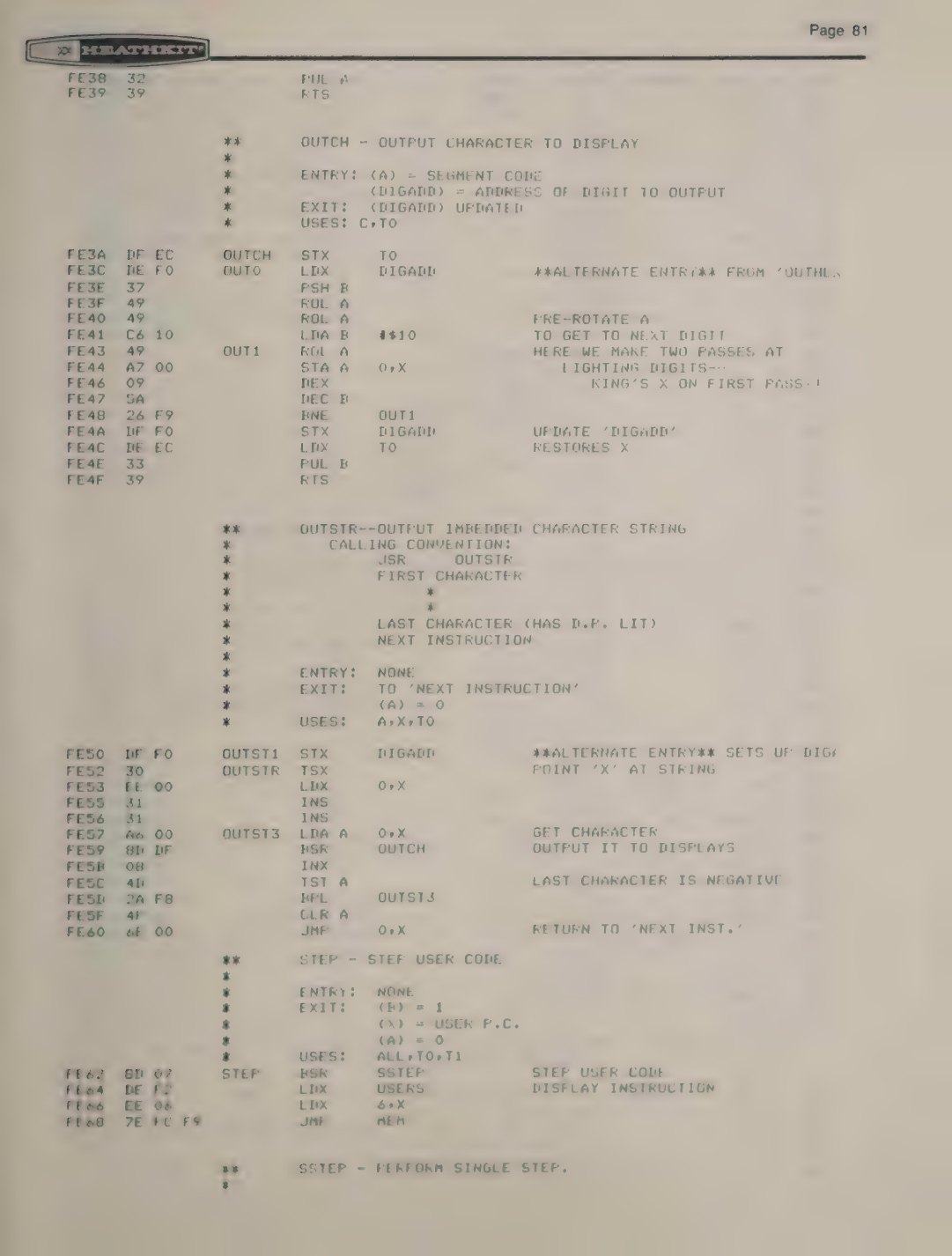
A user program does not have to drive the 48 display latches itself (though it can: volume 2 explains the addresses). The monitor’s routines are documented in the listing with their entry and exit conditions, and the manual’s samples call them by address (ET-3400 manual, 595-2021-03, pp. 65–86). The ones a program needs are:
Table 1 — A user program does not have to drive the 48 display latches itself (though it can: volume 2 explains the addresses). The monitor's routines are documented in the listing with their entry and exit conditions, and the manual's samples call them by address ([ET-3400 manual, 595-2021-03, pp. 65–86](https://archive.org/details/manualsplus11737)). The ones a program needs are
| Name | Address | Does | Entry | Exit |
|---|---|---|---|---|
| REDIS | FCBC | point DIGADD at the leftmost (H) digit | — | DIGADD = C16F |
| OUTCH | FE3A | show one character | A = segment code, DIGADD = digit | DIGADD moved one digit right; A, B, X kept |
| OUTHEX | FE28 | show one hex digit | A low four bits | as OUTCH |
| OUTBYT | FE20 | show a byte as two hex digits | A = byte | DIGADD moved two digits |
| OUTSTR | FE52 | show the string that follows the JSR | bytes after the call, last one with bit 7 (DP) set | returns to the byte after the string; A = 0 |
| OUTSTO | FD8D | REDIS, then OUTSTR | as OUTSTR | as OUTSTR |
| OUTST1 | FE50 | DIGADD = X, then OUTSTR | X = first digit address | as OUTSTR |
| DSPLAY | FD7B | show B bytes from memory as hex | X = address, B = count | X, B kept |
| ENCODE | FDBB | scan the keypad once | — | A = key, carry set if exactly one key is down |
| INCH | FDF4 | wait for a debounced key press | — | A = key value |
| IHB | FE09 | read two keys as a hex byte, echo them | — | A = byte |
| RESET | FC00 | return to the monitor (CPU UP) | — | — |
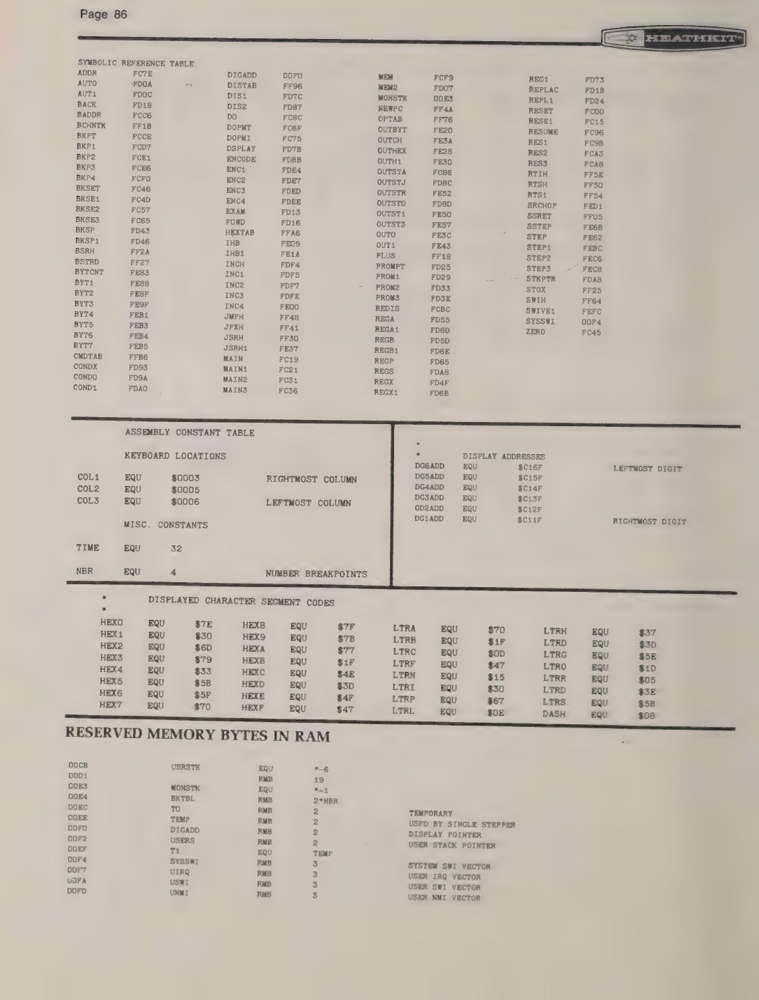
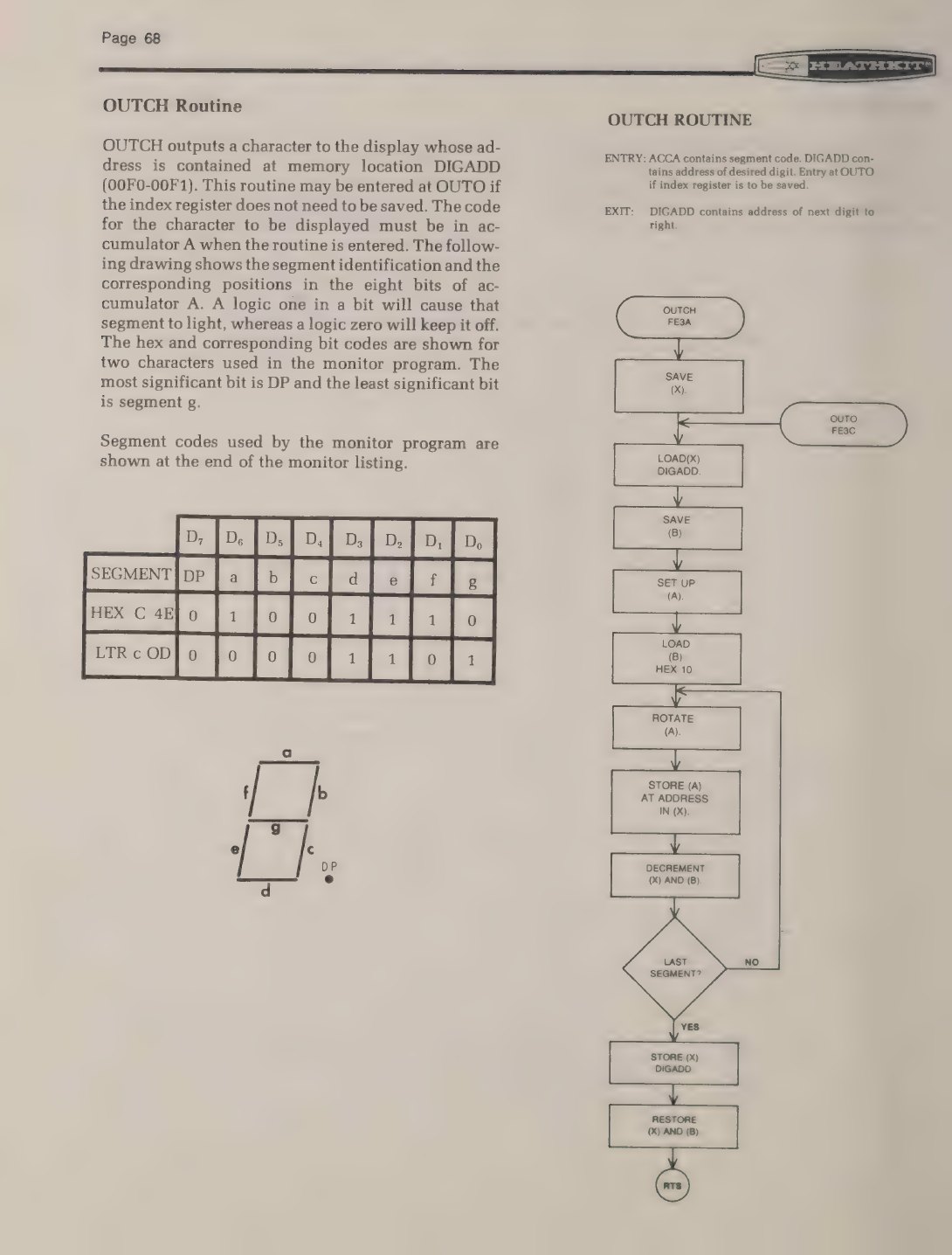
DIGADD is a two-byte pointer at 00F0 that holds the address of the decimal-point latch of the next digit to be written: C16F for H, C15F for I, and so on to C11F for C. Each character moves it down by 10 hex, so after the sixth digit it holds C10F, and the manual’s samples test for C10F to know they have filled the display. Writing to C10F’s range does nothing visible, which is how OUTSTR’s terminator works: a string of six characters plus a seventh byte with only the decimal point set puts that point “in the seventh display position … without actually being displayed” (manual, p. 57).
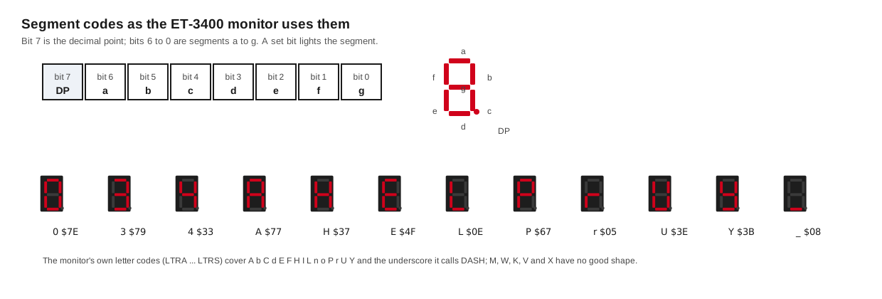
Characters are segment codes, not ASCII: one bit per segment, with bit 7 the decimal point and bits 6 to 0 the segments a to g. The monitor defines the hex digits and a set of letters (LTRA, LTRB, … LTRS), and a programmer made up the rest.
5.2 The manual’s seven samples
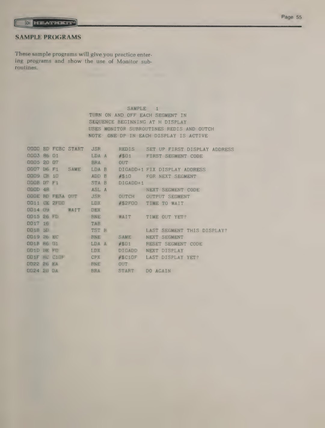
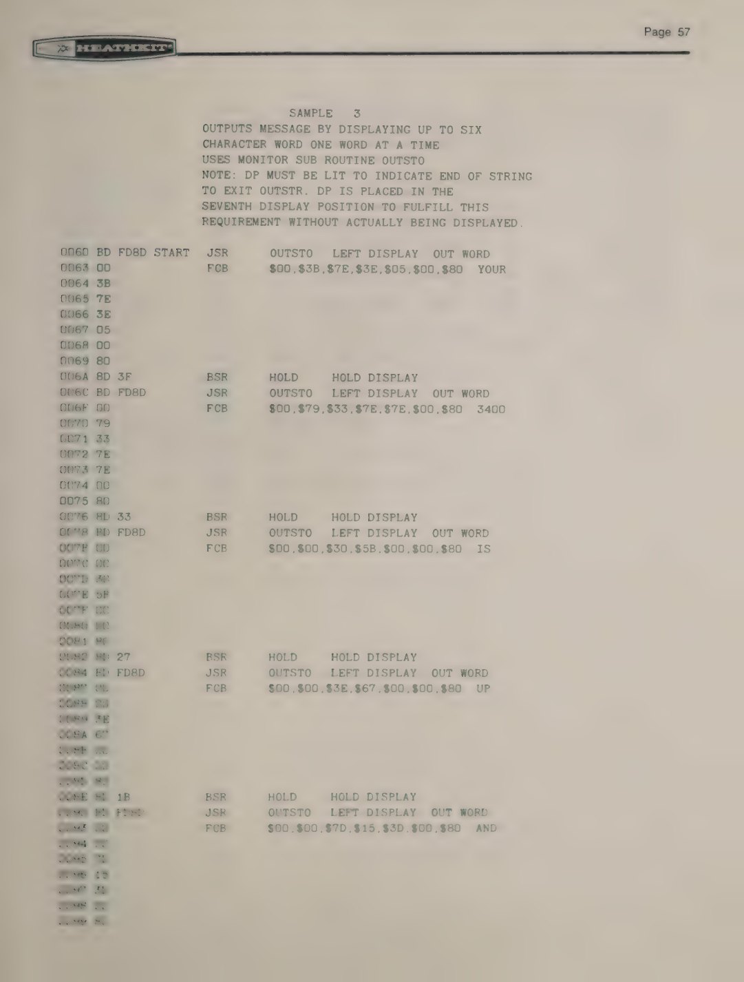
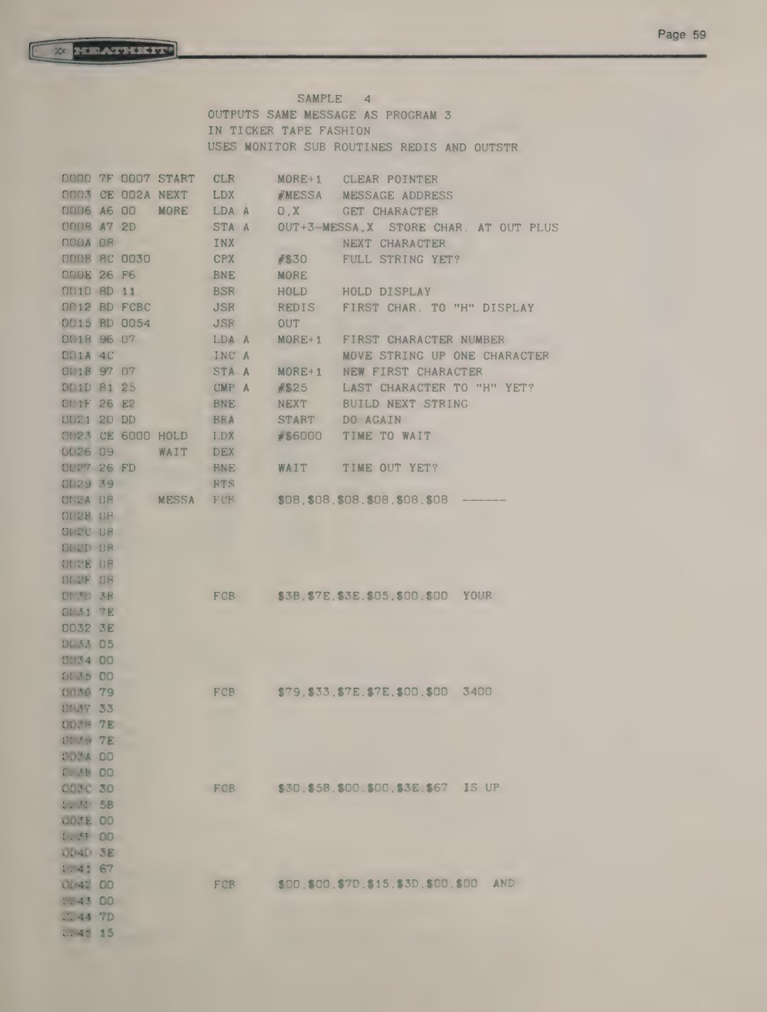
The manual’s “Sample Programs” section has seven programs “to give you practice entering programs and show the use of Monitor subroutines” (manual, pp. 55–64). They are not reproduced here; the pages are shown as figures and the manual is free to read. What each does, and what the emulator shows when it runs the printed bytes, is:
Table 2 — The manual's "Sample Programs" section has seven programs "to give you practice entering programs and show the use of Monitor subroutines" ([manual, pp. 55–64](https://archive.org/details/manualsplus11737)). They are not reproduced here; the pages are shown as figures and the manual is free to read. What each does, and what the emulator shows when it runs the printed bytes, is
| Sample | Address | What it does | Emulator result |
|---|---|---|---|
| 1 | 0000 | lights each segment of each digit in turn, starting at H, using REDIS and OUTCH | H shows g, f, e, d, c, b, a, then the decimal point, then I begins |
| 2 | 0030 | blanks the display, then fills it with the hex value at 0044 (08), and repeats | blank, then 8 8 8 8 8 8, alternating |
| 3 | 0060 | shows the message one word at a time with OUTSTO | YOUR / 3400 / IS / UP / AND / RUNNIN |
| 4 | 0000 | ”outputs same message as program 3 in ticker tape fashion” | the message scrolls in from the right one character per frame |
| 5 | 0060 | a guessing game: a counter runs until a key is held, then the player hunts for the hidden value | ”LO”, “HI” or “YES!” as the guesses go |
| 6 | 0004 | a twelve-hour clock from a timing loop, using DAA | 12:59:59 rolls over to 01 00 00 |
| 7 | 0000 | calculates the offset byte for a relative branch from two addresses | 0D and 5B give 4C, the manual’s own example |
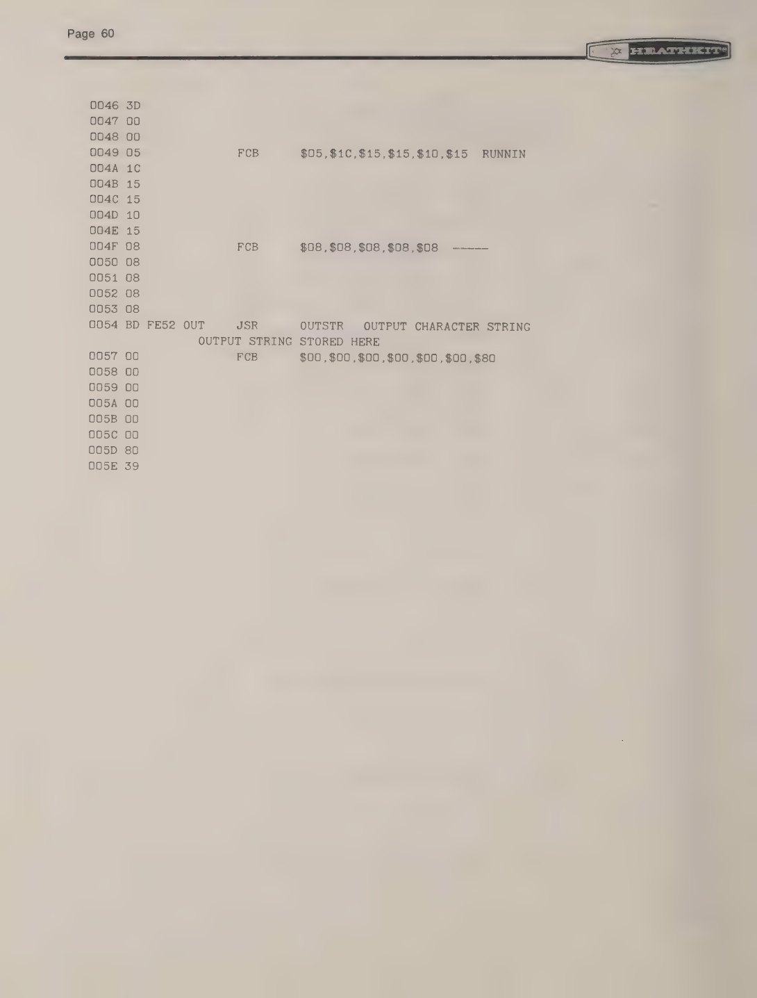
Sample 4 is Heath’s own tickertape, and it is a neat piece of 6800 code. The message (six “dashes”, YOUR 3400 IS UP AND RUNNIN, five more “dashes”) is stored as segment codes. The program copies six of them into the string that follows a JSR OUTSTR, calls it, waits, and moves on one character. It keeps its place by modifying itself: the indexed load LDA A 0,X at 0006 has its offset byte at 0007, and the program clears that byte at the start (CLR MORE+1) and increments it each frame, so the same instruction reads one character further along each time (manual, pp. 59–60). Two details show up in the emulator that are easy to miss on paper. The “dashes” are segment code $08, which is the bottom segment: on the display they are underscores, and the monitor’s own name for that code, DASH, is the same misnomer. And because letters such as O are made from the digit 0’s code ($7E), the emulator’s text reading of the display prints “Y0Ur”, which is what the display really shows.
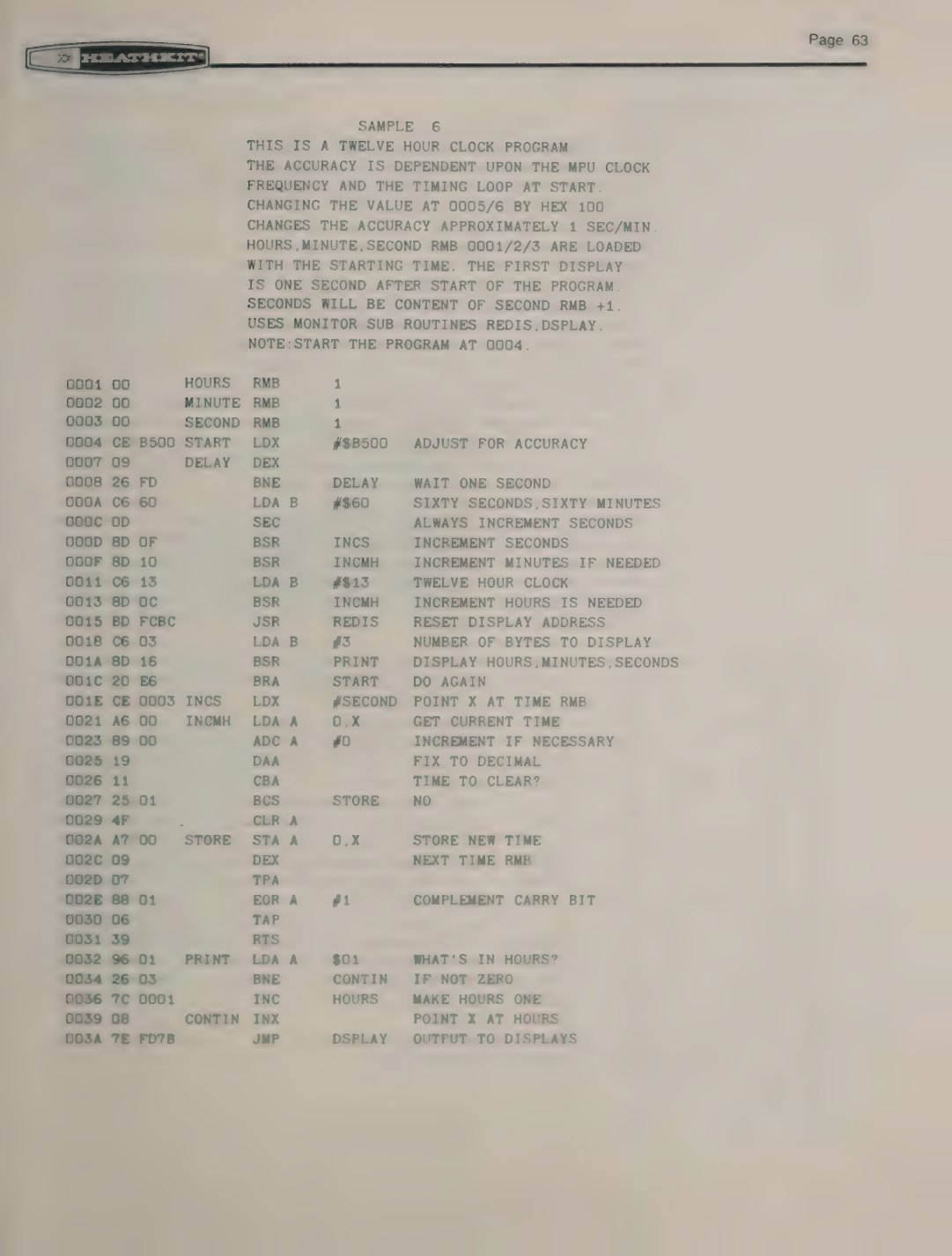
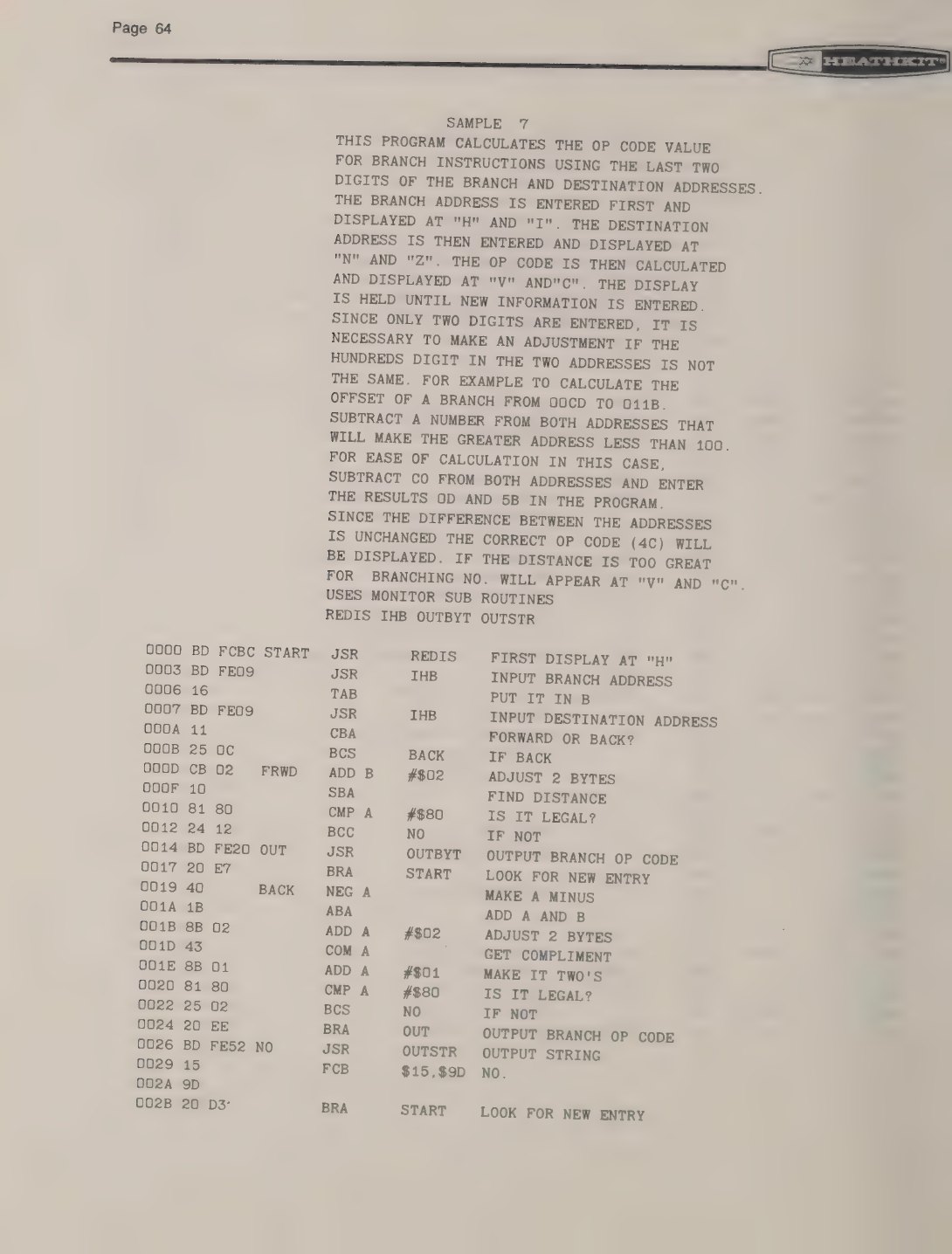
Sample 6 is a lesson in the 6800’s decimal-adjust instruction. Hours, minutes and seconds are kept in BCD at 0001–0003. A subroutine adds the carry with ADC #0, corrects the result with DAA, compares it with a limit (60 for seconds and minutes, 13 for hours) and, by complementing the carry flag through TPA, EOR #1 and TAP, hands the carry on to the next unit. The manual notes that “the accuracy is dependent upon the MPU clock frequency and the timing loop at start”, and that changing the loop constant at 0005–0006 by 100 hex changes the accuracy by about one second a minute (manual, p. 63). Sample 7 is a tool rather than a demonstration: it takes the low bytes of a branch address and a destination from the keypad and shows the offset byte to key in, or “NO.” if the branch is out of range. The manual’s worked example, a branch from 0D to 5B, gives 4C, and so does the emulator.
5.3 Seven programs for this dive
The programs below were written for this dive and are not from Heath’s manuals. They are in Motorola assembler syntax: labels at the left, LDAA/LDAB for the two accumulators, # for an immediate value, $ for hexadecimal, and 0,X for indexed addressing. The assembler chooses direct (one-byte) addresses for page-zero data and extended (two-byte) addresses otherwise. To enter one on a trainer, press AUTO, type the start address 0000, and type the hexadecimal bytes in the second column in order; then press RESET and DO 0000. Each assumes only the standard 256 bytes of RAM.
5.3.1 One segment, by hand
The plainest possible display program writes straight to two latches, as the manual’s operational test does. Data bit 0 is the only bit the latch sees.
                  * Light the decimal point of the H display, then the top bar of the C display.
                  * Each segment is a one-bit latch at C1xx; data bit D0 = 1 turns it on.
0000  86 01       START   LDAA  #$01        ; D0 = 1 means 'on'
0002  B7 C1 6F            STAA  $C16F       ; H display (6), segment address F = decimal point
0005  B7 C1 1E            STAA  $C11E       ; C display (1), segment address E = segment a
0008  3E                  WAI               ; stop (the EE-3401 course calls 3E 'HLT')
The emulator’s display when the program stops (the H decimal point and the top bar of the C digit):
                          _

   .
H    I    N    Z    V    C
5.3.2 A hex counter
OUTBYT shows a byte as two hex digits wherever DIGADD points. Setting DIGADD to C12F, the V digit, puts the count at the right of the display. The delay is a 16-bit count in X: each pass of DEX and BNE takes eight clock cycles, so $2000 passes take about 65,000 cycles, 0.13 seconds at 500 kHz.
                  * Show a byte counting up from 00 on the V and C displays, using OUTBYT.
0000  4F          START   CLRA
0001  36          LOOP    PSHA
0002  CE C1 2F            LDX   #$C12F      ; second digit from the right (V)
0005  DF F0               STX   DIGADD      ; tell the monitor where to write
0007  BD FE 20            JSR   OUTBYT      ; two hex digits, A unchanged
000A  CE 20 00            LDX   #$2000      ; about 0.13 s at 500 kHz
000D  09          WAIT    DEX
000E  26 FD               BNE   WAIT
0010  32                  PULA
0011  4C                  INCA
0012  81 12               CMPA  #$12        ; stop after hex 11 so the run is short
0014  26 EB               BNE   LOOP
0016  3E                  WAI
The first three frames the emulator recorded (the count continues through 0A, 0b, 0C, 0d, 0E and 0F, with b and d in lower case because a seven-segment digit cannot draw B and D):
 0.00 s  "    00"
                     _    _
                    | |  | |
                    |_|  |_|
H    I    N    Z    V    C

 0.13 s  "    01"
                     _
                    | |    |
                    |_|    |
H    I    N    Z    V    C

 0.27 s  "    02"
                     _    _
                    | |   _|
                    |_|  |_
H    I    N    Z    V    C
5.3.3 Decimal arithmetic with DAA
The 6800 adds in binary; DAA (decimal adjust A) corrects the result when both numbers are binary-coded decimal. This program adds 0099 and 0001 as two-byte BCD numbers. The low bytes give 9A in binary, which DAA turns into 00 with a carry; ADCA carries it into the high bytes. DSPLAY then shows the two result bytes as four digits.
                  * 0099 + 0001 in BCD: the low bytes give 00 with a carry, so the sum is 0100.
0000  B6 00 21    START   LDAA  N1+1
0003  BB 00 23            ADDA  N2+1        ; low bytes
0006  19                  DAA               ; decimal adjust
0007  B7 00 25            STAA  SUM+1
000A  B6 00 20            LDAA  N1
000D  B9 00 22            ADCA  N2          ; high bytes plus the carry
0010  19                  DAA
0011  B7 00 24            STAA  SUM
0014  BD FC BC            JSR   REDIS       ; first digit
0017  CE 00 24            LDX   #SUM
001A  C6 02               LDAB  #2          ; two bytes = four digits
001C  BD FD 7B            JSR   DSPLAY
001F  3E                  WAI
0020  00 99       N1      FCB   $00,$99
0022  00 01       N2      FCB   $00,$01
0024  00 00       SUM     FCB   0,0
_ _ _
| | | | | | |
|_| | |_| |_|
H I N Z V C5.3.4 A running light
OUTCH always moves DIGADD one digit to the right. To light and then blank the same digit, this program puts DIGADD back by adding 10 hex to its low byte; to move left, it adds 20 hex. A bottom bar runs left to right, then a top bar runs back.
                  * A bottom bar walks left to right across the six displays, then a top bar
                  * walks back.  OUTCH always moves DIGADD one display to the right, so the
                  * program adds $10 or $20 to DIGADD's low byte to stay put or step left.
0000  BD FC BC    START   JSR   REDIS       ; DIGADD -> H display (C16F)
0003  C6 06               LDAB  #6
0005  86 08       RIGHT   LDAA  #$08        ; segment d, the bottom bar
0007  8D 1A               BSR   SHOW        ; light, wait, blank; DIGADD ends one place right
0009  5A                  DECB
000A  26 F9               BNE   RIGHT
000C  96 F1               LDAA  DIGADD+1    ; DIGADD is now C10F; back up to C11F (C display)
000E  8B 10               ADDA  #$10
0010  97 F1               STAA  DIGADD+1
0012  C6 06               LDAB  #6
0014  86 40       LEFT    LDAA  #$40        ; segment a, the top bar
0016  8D 0B               BSR   SHOW
0018  96 F1               LDAA  DIGADD+1    ; two places left of where SHOW left it
001A  8B 20               ADDA  #$20
001C  97 F1               STAA  DIGADD+1
001E  5A                  DECB
001F  26 F3               BNE   LEFT
0021  20 DD               BRA   START
0023  37          SHOW    PSHB
0024  BD FE 3A            JSR   OUTCH       ; light it (DIGADD moves one place right)
0027  CE 30 00            LDX   #$3000      ; about 0.2 s
002A  09          W1      DEX
002B  26 FD               BNE   W1
002D  96 F1               LDAA  DIGADD+1    ; step back to the same digit
002F  8B 10               ADDA  #$10
0031  97 F1               STAA  DIGADD+1
0033  4F                  CLRA
0034  BD FE 3A            JSR   OUTCH       ; and blank it again
0037  33                  PULB
0038  39                  RTS
The first frames, about 0.2 seconds apart:
 0.00 s  "_     "


 _
H    I    N    Z    V    C

 0.20 s  " _    "


      _
H    I    N    Z    V    C

 0.40 s  "  _   "


           _
H    I    N    Z    V    C
5.3.5 Reading the keypad
INCH waits for a key and returns its value; OUTHEX shows it. Six key presses fill the display. In the emulator the keys are scripted (here 3, 4, 0, 0, E, 7).
                  * Wait for a key with INCH and show it, filling the display left to right.
0000  BD FC BC    START   JSR   REDIS
0003  C6 06               LDAB  #6
0005  BD FD F4    NEXT    JSR   INCH        ; A = value of the key pressed
0008  BD FE 28            JSR   OUTHEX      ; show it at DIGADD
000B  5A                  DECB
000C  26 F7               BNE   NEXT
000E  3E                  WAI
_ _ _ _ _
_| |_| | | | | |_ |
_| | |_| |_| |_ |
H I N Z V C5.3.6 A word on the display
OUTSTO takes its string from the bytes after the JSR. Six characters fill the display, and the seventh byte, $80, ends the string with its decimal point off the end of the display.
                  * OUTSTO starts at the H display and copies segment codes until it meets
                  * one with the decimal point set.  The seventh byte carries that point
                  * off the end of the display, so it is never seen.
0000  BD FD 8D    START   JSR   OUTSTO
0003  37 4F 0E            FCB   $37,$4F,$0E,$0E,$1D,$00,$80   ; H E L L O blank, end
0006  0E 1D 00
0009  80
000A  3E                  WAI
_
|_| |_ | | _
| | |_ |_ |_ |_|
H I N Z V C5.4 The tickertape
A tickertape program scrolls a message across the display, entering at the right and leaving at the left, like the moving-text sign on a stock exchange. It is the natural showpiece for a six-digit display, because a message longer than six characters can only be read by moving it. Heath’s Sample 4 is one; this one is written differently so that the message can be any length and the program does not modify itself.
The message is a table of segment codes, with six blanks before it and six after so that it scrolls in from an empty display and out to one. A counter, POS, holds the position of the first character in a six-character window. Each frame:
- points X at the message and steps it forward POS times;
- copies six codes from there into a buffer, BUF, using two pointers kept in RAM (the 6800 has only one index register, so copying from one place to another means saving and reloading X);
- calls REDIS and then a tiny routine, SHOW, whose body is
JSR OUTSTRfollowed by the buffer and a terminating $80: OUTSTR draws the six characters and returns past the terminator to an RTS; - waits about a third of a second with a
DEX/BNEloop; - increments POS, and goes round again until the last window has been shown.
The message text is turned into segment codes by the assembler’s FCS pseudo-op, a convenience of this dive’s tool; on a real trainer one keys in the bytes shown in the listing. The seven-segment font has no good M, W, K, V or X, so the message avoids them, and T has to be the lower-case t.
                  * A message scrolls right to left across the six displays, like a stock
                  * ticker.  TEXT holds one segment code per character, with six blanks
                  * leading in and six trailing out.  Each frame copies a six-character
                  * window into BUF, which ends with a byte whose decimal point is set, and
                  * OUTSTR draws it.  Then the window moves one character and repeats.
                  * (FCS is this simulator's pseudo-op for "form constant segments": it turns
                  * text into seven-segment codes.  The listing shows the bytes to key in.)
                  POS     EQU   $00B0       ; first character of the window
                  SRC     EQU   $00B1       ; source pointer (2 bytes)
                  DST     EQU   $00B3       ; destination pointer (2 bytes)
0000  7F 00 B0    START   CLR   POS
0003  CE 00 4A    FRAME   LDX   #TEXT       ; X = TEXT + POS
0006  D6 B0               LDAB  POS
0008  27 04       SKIP    BEQ   COPY
000A  08                  INX
000B  5A                  DECB
000C  20 FA               BRA   SKIP
000E  DF B1       COPY    STX   SRC
0010  CE 00 42            LDX   #BUF
0013  DF B3               STX   DST
0015  C6 06               LDAB  #6          ; six characters
0017  DE B1       MOVE    LDX   SRC
0019  A6 00               LDAA  0,X
001B  08                  INX
001C  DF B1               STX   SRC
001E  DE B3               LDX   DST
0020  A7 00               STAA  0,X
0022  08                  INX
0023  DF B3               STX   DST
0025  5A                  DECB
0026  26 EF               BNE   MOVE
0028  BD FC BC            JSR   REDIS       ; DIGADD -> H display
002B  BD 00 3F            JSR   SHOW        ; draw the window
002E  CE 50 00            LDX   #$5000      ; hold the frame about a third of a second
0031  09          HOLD    DEX
0032  26 FD               BNE   HOLD
0034  7C 00 B0            INC   POS         ; slide the window one character
0037  96 B0               LDAA  POS
0039  81 1F               CMPA  #LEN-5      ; past the last window?
003B  26 C6               BNE   FRAME
003D  20 C1               BRA   START       ; round again
003F  BD FE 52    SHOW    JSR   OUTSTR      ; OUTSTR's string is the buffer that follows
0042  00 00 00    BUF     RMB   6
0045  00 00 00
0048  80                  FCB   $80         ; DP set: ends the string, off the end of the display
0049  39                  RTS
004A  00 00 00    TEXT    FCS   "      HEATH ET-3400 SAYS HELLO      "
004D  00 00 00
0050  37 4F 77
0053  0F 37 00
0056  4F 0F 01
0059  79 33 7E
005C  7E 00 5B
005F  77 3B 5B
0062  00 37 4F
0065  0E 0E 1D
0068  00 00 00
006B  00 00 00
                  LEN     EQU   *-TEXT
The emulator runs it at 500 kHz. Each frame is held for about 0.33 seconds, so the 31 frames of this message take a little over ten seconds before it starts again. These are the frames as the emulator recorded them:
 0.34 s  "     H"

                         |_|
                         | |
H    I    N    Z    V    C

 0.67 s  "    HE"
                          _
                    |_|  |_
                    | |  |_
H    I    N    Z    V    C

 1.00 s  "   HEA"
                     _    _
               |_|  |_   |_|
               | |  |_   | |
H    I    N    Z    V    C

 1.34 s  "  HEAt"
                _    _
          |_|  |_   |_|  |_
          | |  |_   | |  |_
H    I    N    Z    V    C

 1.67 s  " HEAtH"
           _    _
     |_|  |_   |_|  |_   |_|
     | |  |_   | |  |_   | |
H    I    N    Z    V    C

 2.00 s  "HEAtH "
      _    _
|_|  |_   |_|  |_   |_|
| |  |_   | |  |_   | |
H    I    N    Z    V    C

 2.34 s  "EAtH E"
 _    _                   _
|_   |_|  |_   |_|       |_
|_   | |  |_   | |       |_
H    I    N    Z    V    C

 2.67 s  "AtH Et"
 _                   _
|_|  |_   |_|       |_   |_
| |  |_   | |       |_   |_
H    I    N    Z    V    C

 3.00 s  "tH Et-"
                _
|_   |_|       |_   |_    _
|_   | |       |_   |_
H    I    N    Z    V    C

 3.33 s  "H Et-3"
           _              _
|_|       |_   |_    _    _|
| |       |_   |_         _|
H    I    N    Z    V    C

 3.67 s  " Et-34"
      _              _
     |_   |_    _    _|  |_|
     |_   |_         _|    |
H    I    N    Z    V    C

 4.00 s  "Et-340"
 _              _         _
|_   |_    _    _|  |_|  | |
|_   |_         _|    |  |_|
H    I    N    Z    V    C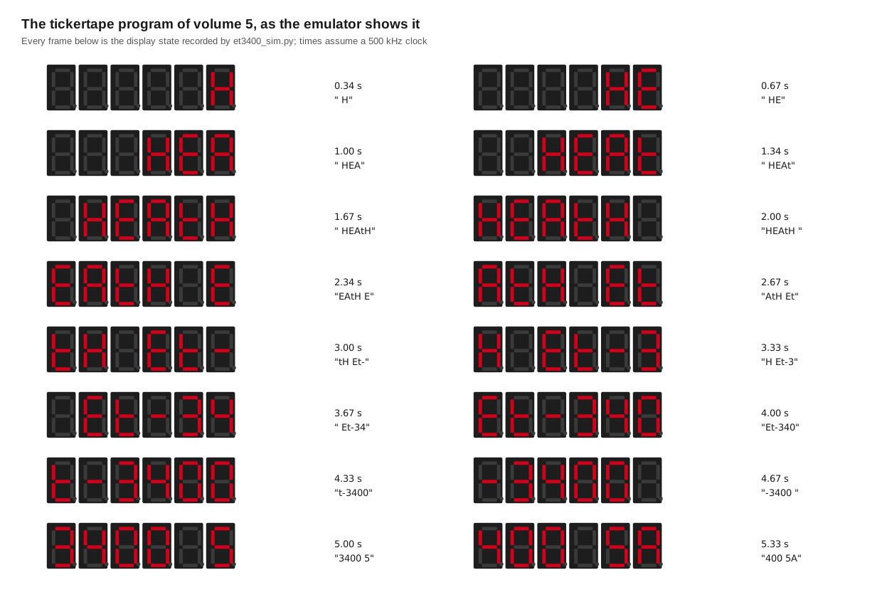
On a trainer modified for the ETA-3400, which runs at 1 MHz, the same program scrolls twice as fast; the hold constant $5000 would be doubled to keep the speed. A tickertape for an audience, such as a classroom, is mostly a question of choosing that speed and a message that the seven-segment font can spell.
5.5 Running the programs yourself
The emulator needs only Python 3. From 03-outputs/tools/:
python3 et3400_sim.py --selftest          # 33 checks against published vectors
python3 et3400_sim.py --list              # the programs in this volume
python3 et3400_sim.py --listing tickertape
python3 et3400_sim.py --run tickertape --frames 40
python3 et3400_sim.py --run keyecho --keys 3400E7
Its limits are stated in the file. It models the 6800 completely (all 197 documented op codes, their flags and their cycle counts), the RAM, the display latches and the keypad matrix. It stubs the monitor routines by behaviour, with approximate cycle counts, rather than running Heath’s code, so programs that call into the middle of a monitor routine, or that depend on its exact timing, may behave differently. The keypad commands (EXAM, AUTO, SS and the rest) are not emulated; programs are loaded directly into memory. The breadboard, LEDs and switches are panel wiring, not memory, and are not modelled.
Sources
- Heath Company. Heathkit Manual for the Microprocessor Trainer, Model ET-3400, 595-2021-03, © 1977: Sample Programs (pp. 55–64), subroutine flowcharts (pp. 65–72), monitor listing (pp. 73–86). Internet Archive (DLARC). https://archive.org/details/manualsplus_11737
- Heathkit Educational Systems. Microprocessors, EB-6401A, Experiment 3. https://archive.org/details/6800-Microprocessors-Book-1and-2-Heathkit-1985
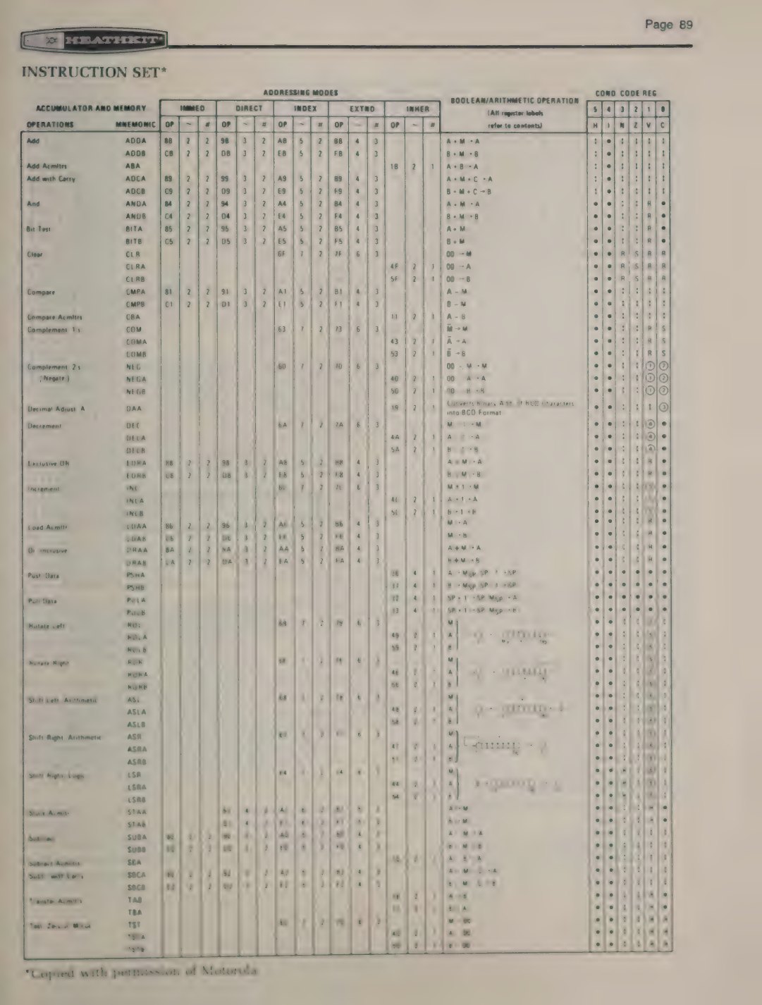
- Motorola. M6800 Programming Reference Manual (instruction set and condition-code rules), summarised in the ET-3400 manual’s “Instruction Set” pages (pp. 89–90).
et3400_sim.py, written for this dive:Heathkit/Education/ET-3400-Microprocessor-Trainer/03-outputs/tools/.
Comments (0)