HW-101 Transceiver · Volume 3
Building the Kit
What arrived from Benton Harbor was a large carton containing seven numbered packages, an eighth pack of everything too big for a bag, a chassis, a front panel, a cabinet, a pre-cut wiring harness, twenty tubes and a 245-page manual. What left the workbench several weeks later was a transceiver. The distance between those two states is the actual product Heath was selling, and the HW-101’s manual is a good specimen of the company’s method at its most developed: eight parts lists, thirty-odd fold-out pictorials, a flow-chart layout for every assembly step, and a tone that assumes nothing at all about the builder’s experience except that he can be trusted to check off a box.

3.1 How the manual is organised
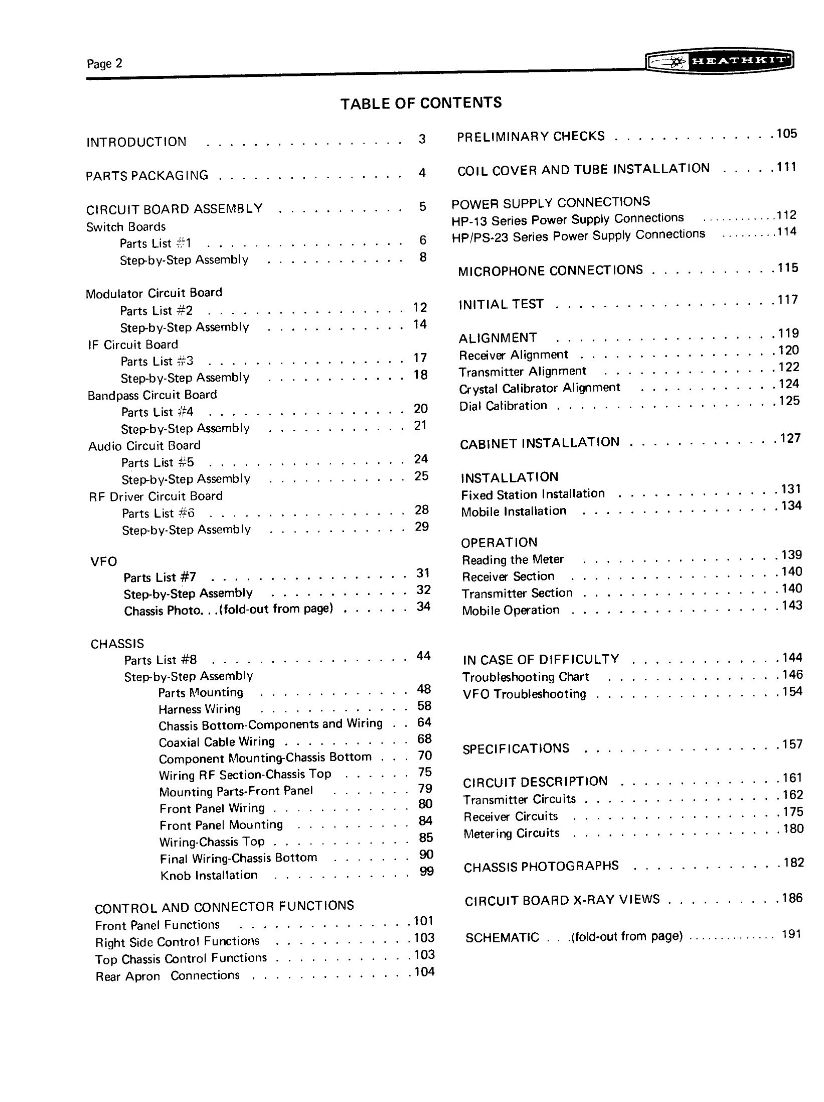
The contents page is the shape of the build. Seven circuit-board assemblies come first, each with its own parts list and step-by-step section; then the chassis, in nine stages; then the checks, the alignment, the cabinet, and only then the sections on installing and operating the finished rig.
Table 1 — How the manual is organised
| Section | Manual pages |
|---|---|
| Introduction and parts packaging | 3–4 |
| Circuit board assembly: switch boards, modulator, IF, bandpass, audio, RF driver, VFO | 5–33 |
| Chassis photograph (fold-out) | 34 |
| Chassis: parts mounting, harness wiring, bottom components, coaxial cable, RF section, front panel, final wiring, knobs | 44–100 |
| Control and connector functions | 101–104 |
| Preliminary checks | 105–110 |
| Coil cover and tube installation | 111 |
| Power supply and microphone connections | 112–116 |
| Initial test | 117–118 |
| Alignment, including dial calibration | 119–125 |
| Cabinet installation, fixed and mobile installation | 127–138 |
| Operation | 139–143 |
| In case of difficulty, troubleshooting chart, VFO troubleshooting | 144–156 |
| Specifications and circuit description | 157–181 |
| Chassis photographs, X-ray views, schematic | 182 onward |
The ordering is deliberate. Everything that can be built and inspected on the bench is built first, while the chassis is still an empty box and mistakes are cheap to correct. The parts that will be hard to reach later — components under the switch wafers, the wiring harness, the coaxial cables — go in before the boards are mounted over them. And the manual withholds the tubes until page 111, after the preliminary resistance checks, so that a wiring error cannot destroy anything on first power-up.
3.2 Parts packaging
Heath’s packing scheme is a piece of process design in its own right. The parts arrive in seven numbered packages corresponding to the seven parts lists, plus “pack #8” holding the large items and everything used in chassis assembly. Each assembly section opens by telling the builder which numbered pack to open, and the manual is emphatic about the discipline this requires: every other pack stays sealed until a parts list calls for it, so that parts cannot become intermixed.
The reasoning is not fussiness. A 1 kΩ and a 10 kΩ resistor differ by one colour band; twenty-five loose resistors from three different packs on the same bench is how a kit becomes a repair job. A part packed in an individual envelope with a number on it is to be returned to its envelope after identification, until called for.

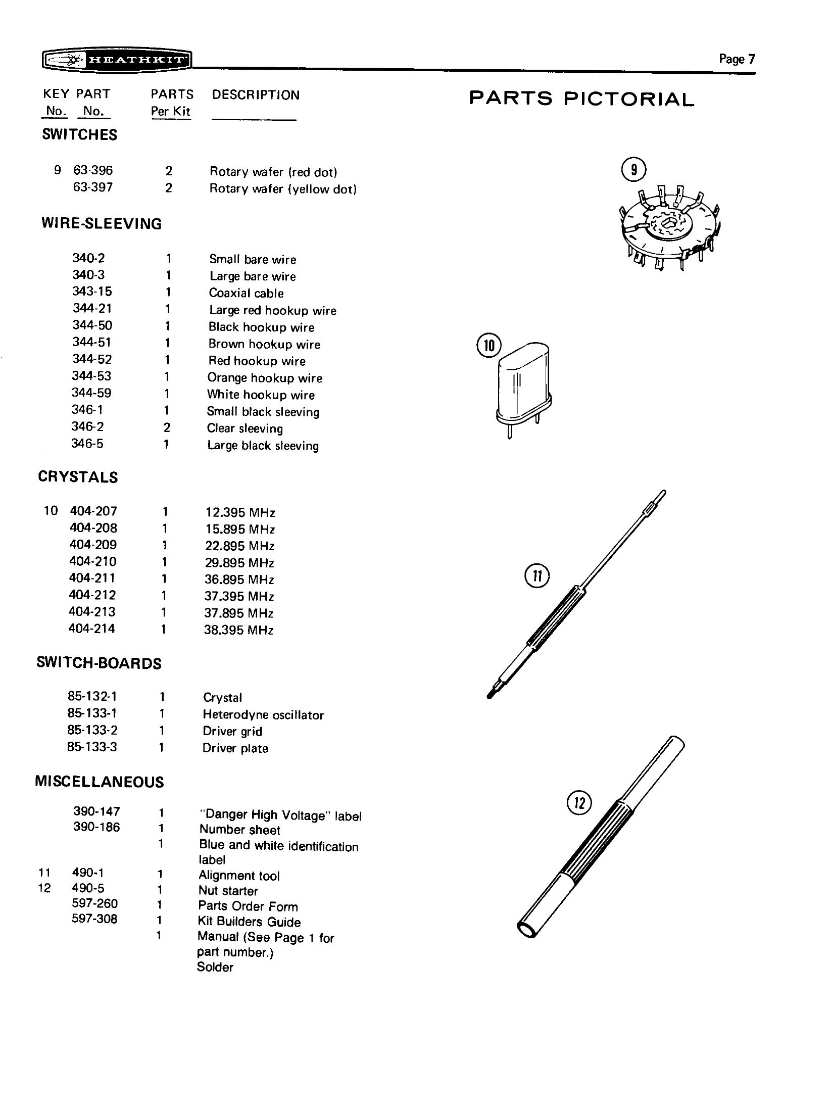
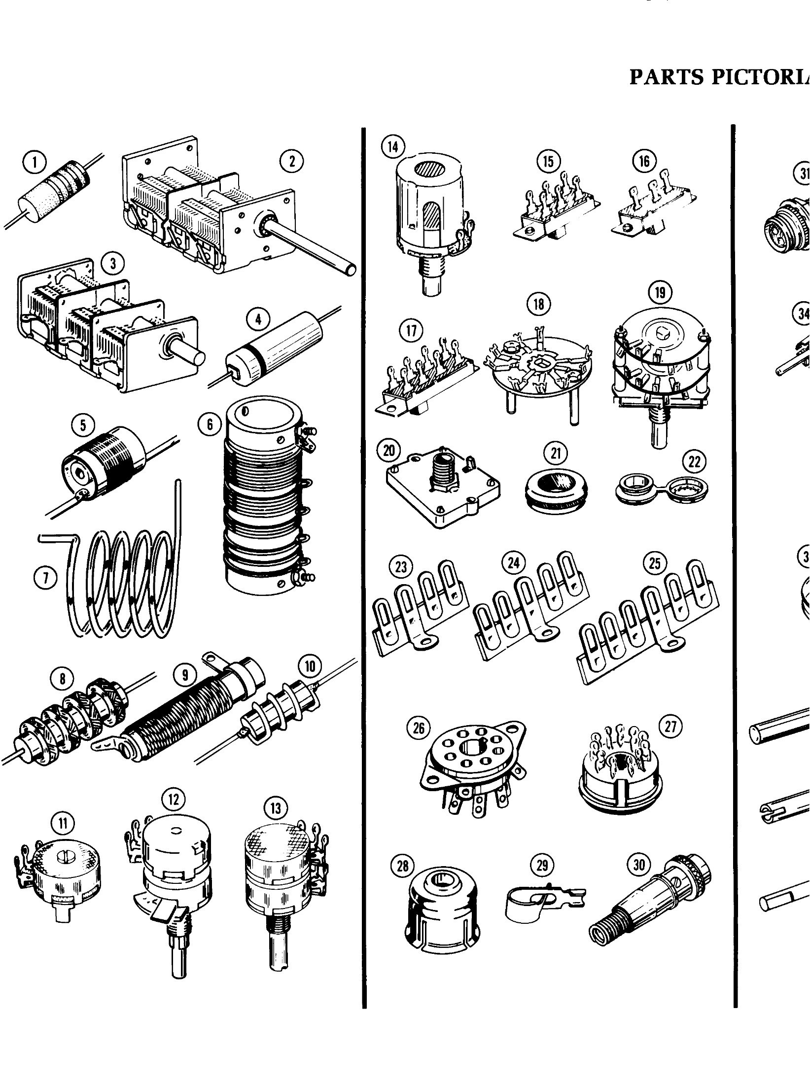
Each parts list is paired with a “Parts Pictorial” — a page of line drawings, actual size where possible, showing what each component looks like. This is the part of the Heath method that separates it from every other kit of the era: the builder identifies parts by comparing them with a drawing rather than by reading a colour code he may never have seen before. Every page of the assembly sections also carries a printed six-inch ruler along the bottom edge, for measuring leads, sleeving and wire.
3.3 The first step is a crystal switch-board
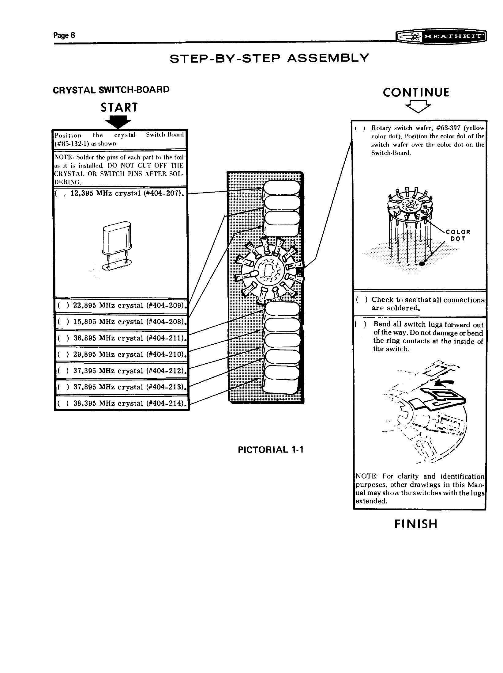
The HW-101’s assembly begins, unusually, with the crystal switch-board: a small printed board that carries the eight heterodyne oscillator crystals and has a rotary switch wafer soldered directly onto it. Three more switch-boards follow — heterodyne oscillator, driver grid and driver plate — and each is a switch wafer married to a board carrying the coils, capacitors and crystals that wafer selects.
The arrangement is a genuine cost and reliability innovation, and Heath sold it as such: the Christmas 1975 catalogue copy lists “circuit boards, wiring harness, and ‘Switch-Boards’” as the three things that make the kit go together quickly. Instead of a spider’s web of hand-wired point-to-point connections around a bandswitch — the traditional way, and the traditional source of stray capacitance, microphony and building errors — the components sit on a board a few millimetres from the wafer lugs, in the same place in every unit built.
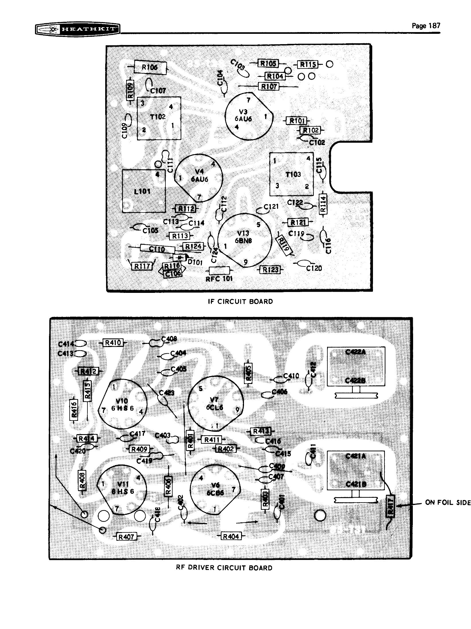
Five larger boards follow: modulator, IF, bandpass, audio and RF driver, then the VFO, which is built as a sub-assembly inside its own shielded box. Each is a straightforward exercise in resistors, capacitors, coils and tube sockets, and each ends with a check step. A builder who stops there has seven completed assemblies, none of which can be tested yet.
3.4 The chassis
Chassis work is where the HW-101 becomes a substantial project. It runs from page 44 to page 100 and divides into nine phases: mounting hardware, harness wiring, components under the chassis, coaxial cables, the RF section on top of the chassis, front-panel parts, front-panel wiring, panel mounting, and the final wiring.
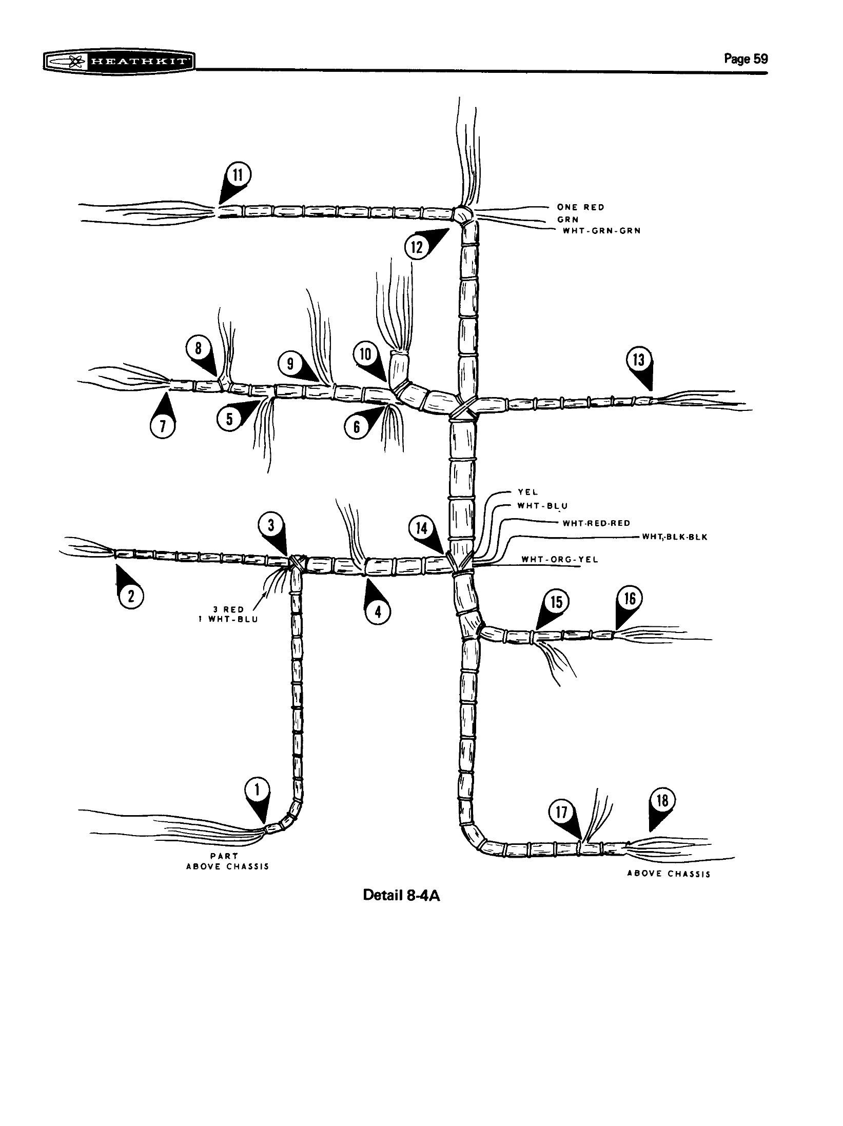
The wiring harness is pre-cut and colour-coded, and laying it in is one of the few operations in the kit that cannot be undone easily. The manual’s harness pictorial shows the whole loom flattened out with every breakout labelled; the builder dresses it into the chassis, then connects branches one wire at a time over several pages. A harness laid in the wrong orientation is hours of unpicking.
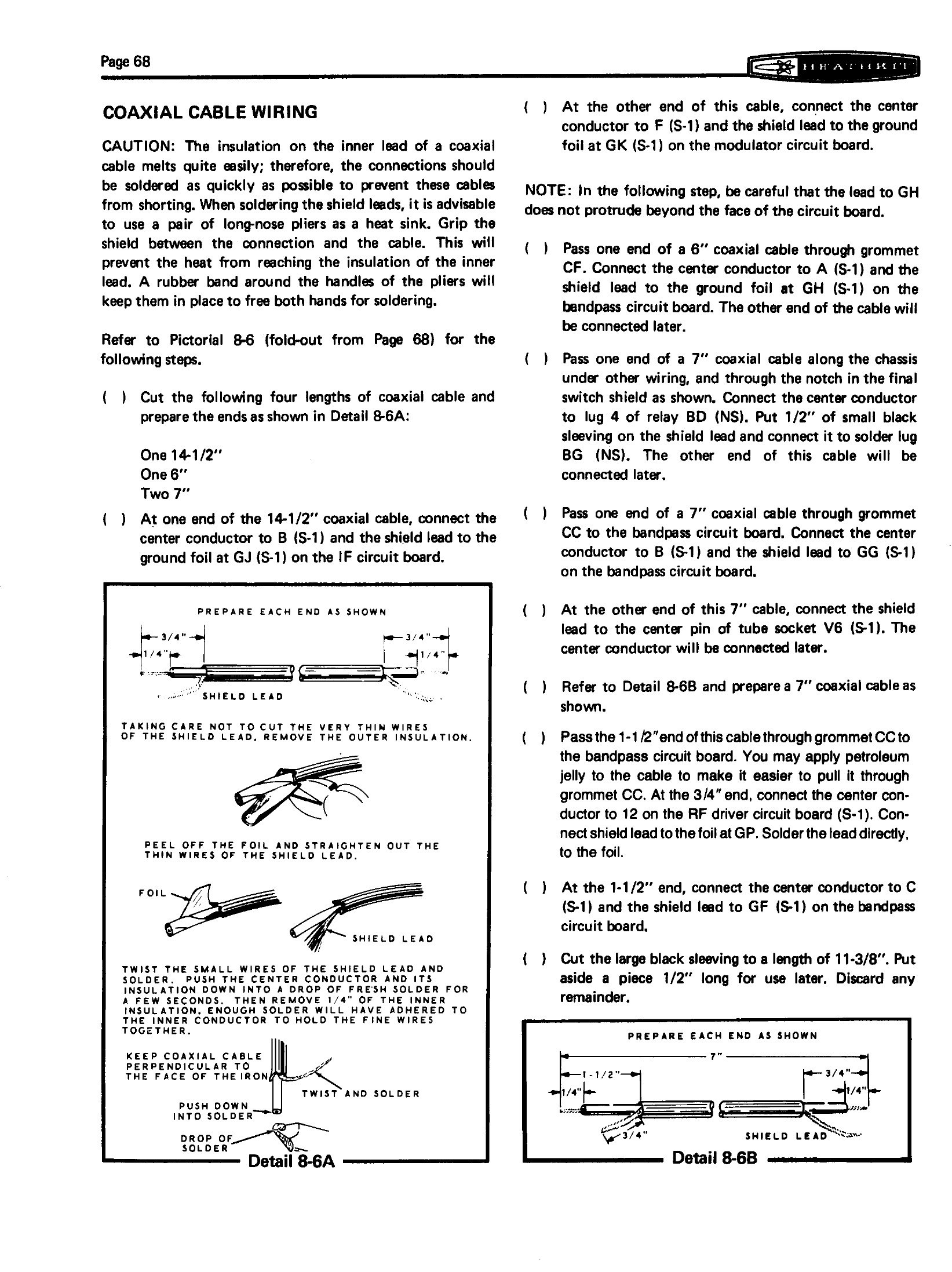
The coaxial cable wiring is the section most likely to produce a subtle fault. Four lengths of miniature coax — one 14½-inch, one 6-inch and two 7-inch — carry signals between the boards, and the manual devotes a full detail drawing to preparing the ends, along with a caution that the inner insulation melts easily and a suggestion to clamp long-nose pliers on the braid as a heat sink, held closed with a rubber band so that both hands stay free. A melted dielectric here shows up later as low sensitivity or unstable transmit, and looks like nothing at all on inspection.
The RF section on top of the chassis is mechanical work: the final amplifier cage, the two large air-variable capacitors of the driver preselector, the pi-network tank coil, the relays and the VFO box. Two jobs in this area have long-term consequences.
The first is the driver preselector drive. The preselector capacitors are turned by rubber belts running over pulleys, and the pulleys are soldered to their shafts. Half a century later, both halves of that arrangement are the commonest mechanical failures in the rig — perished belts, and pulleys that have come loose because the builder’s iron could not heat the shaft enough to make a proper joint. The restoration volume returns to this.
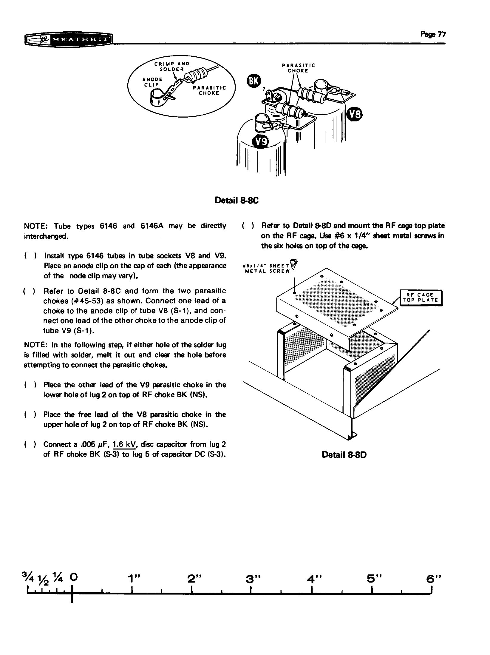
The second is the final amplifier. The two 6146s take anode caps rather than top-cap-free connections, and a pair of parasitic chokes is formed and soldered between the anode clips and the plate choke. The manual notes at this point that “tube types 6146 and 6146A may be directly interchanged” — a sentence that would be revised by a service bulletin eight years later, when the newer 6146B turned out not to be interchangeable at all.
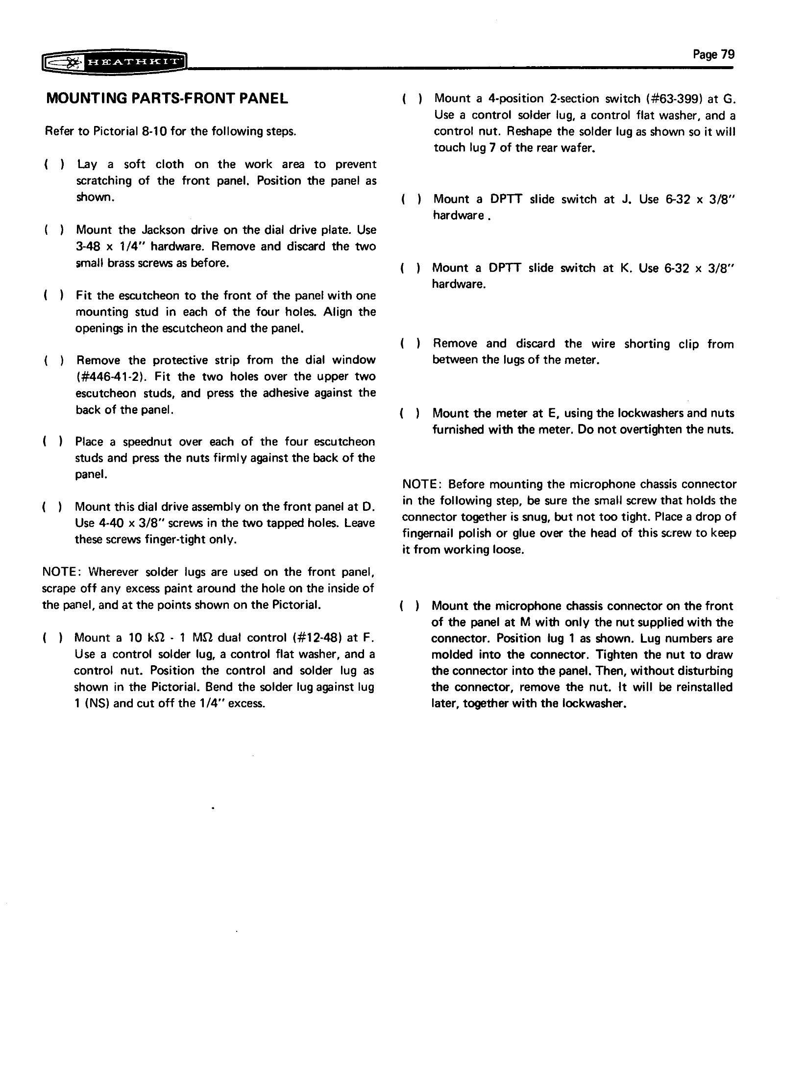
The front panel is the last mechanical assembly and the one that decides how the finished rig feels to use. The escutcheon, the dial window and the dial-drive plate go on first, and then, in a single unremarkable step, the component that distinguishes the HW-101 from its predecessor: “Mount the Jackson drive on the dial drive plate.” The ball-bearing planetary drive bought in from Jackson Brothers is what replaced the HW-100’s Harmonic Drive, and it is what gives the 36-to-1 ratio and 35⅓ revolutions per 500 kHz segment that the catalogue advertised. The manual also warns against overtightening the meter nuts and instructs the builder to put a drop of nail polish on the microphone connector screw to keep it from working loose.
3.5 Checks before power
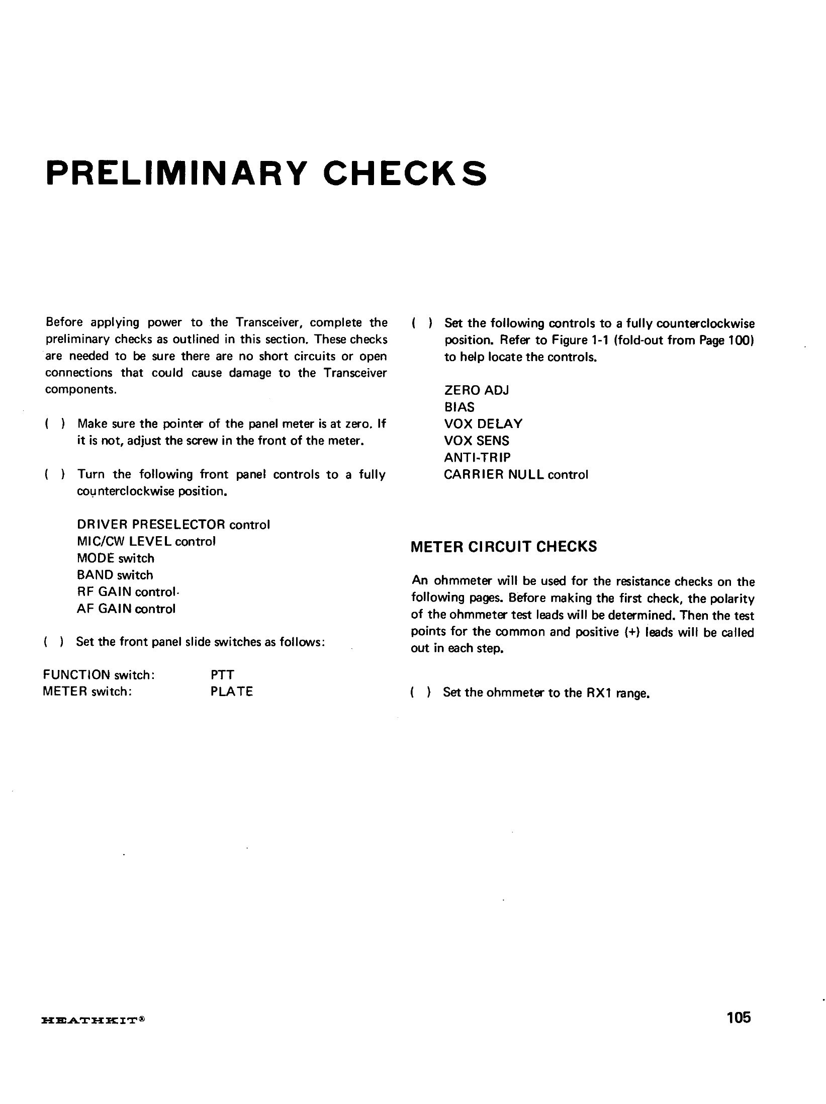
Heath’s ordering of the last stages is the part of the method that most repays attention. The builder finishes the wiring, installs the knobs, and then does not switch on. Instead, pages 105 to 110 are preliminary checks: a visual inspection for solder bridges and unsoldered joints, and a set of resistance measurements taken with an ohmmeter against a printed table. Only when those pass does the manual allow the coil covers and the tubes to be fitted, on page 111.
Then the power supply is connected — the HP-13 series for mobile, the HP-23 or PS-23 series for fixed station, each with its own wiring section — the microphone is wired, and the initial test on pages 117 and 118 brings the set to life for the first time, band by band, with the meter as the only instrument.
3.6 What it took
Heath never published a build time for the HW-101 in any catalogue or manual examined here, and figures quoted in forums vary so widely that none of them is worth repeating as fact. What the manual itself implies is a substantial commitment: eight parts lists, roughly ninety pages of numbered assembly steps, more than thirty pictorials, several hundred soldered joints on the boards alone and several hundred more on the chassis. It is a kit for evenings across several weeks, not a weekend.
The tools are modest, and the manual refers the builder to the separate “Kit Builders Guide” booklet for the basics. A 25 to 40 watt pencil iron and rosin-core solder; long-nose pliers and diagonal cutters; nut drivers and screwdrivers; an ohmmeter for the preliminary checks. Alignment needs more, and that is the subject of the next volume: a 50 Ω dummy load, a high-impedance voltmeter, an RF wattmeter or SWR bridge, alignment tools for the coil slugs, and — optionally — a frequency counter for the VFO.
3.7 What a finished kit looks like
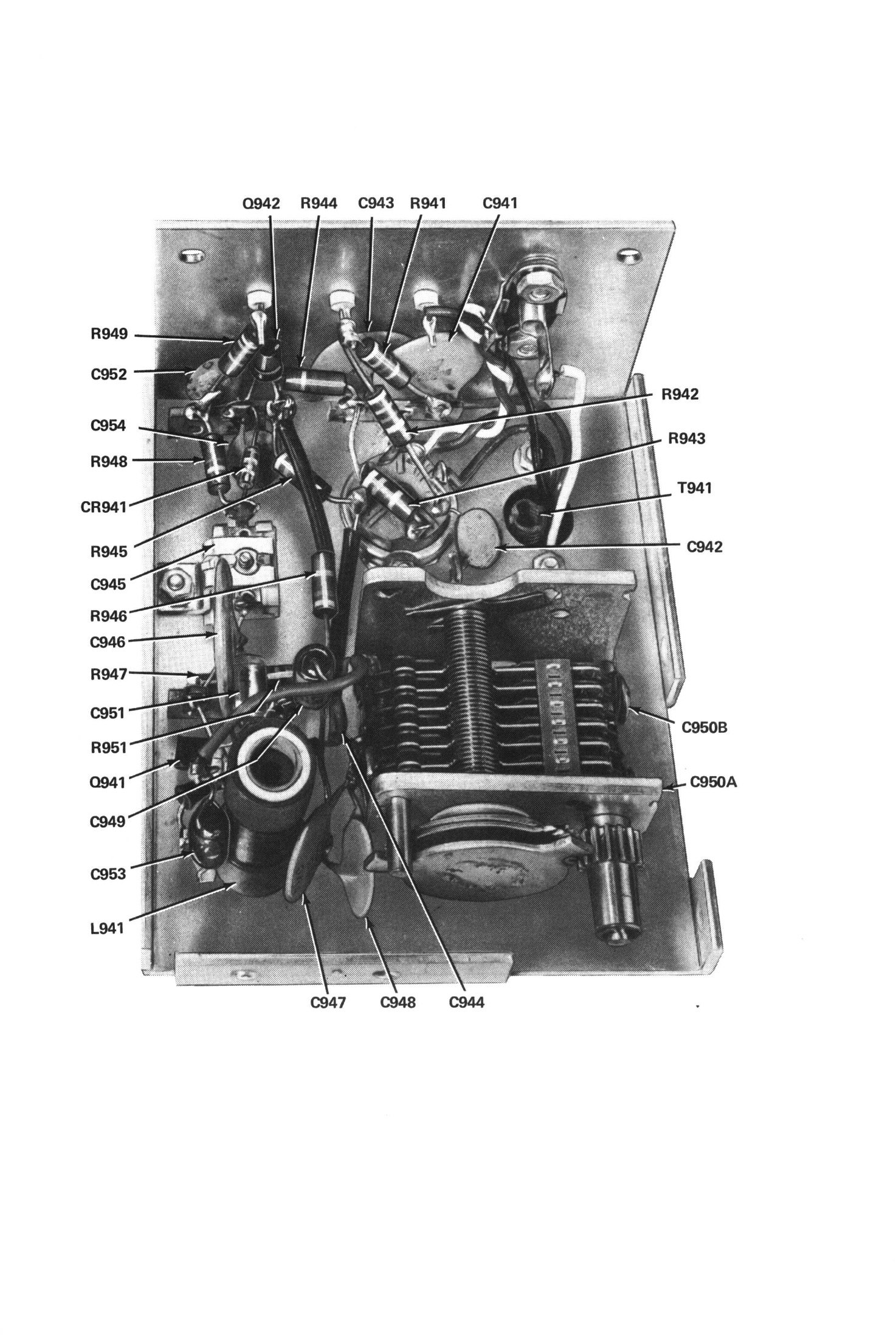
The two views that matter for judging a built HW-101 are the top of the chassis and the underside. The top should show five boards square to the chassis, coil cans upright, coax dressed away from the RF section, and the final cage closed. The underside should show the harness laid in neat runs with the branches broken out where the pictorial puts them, no long free-standing leads, and solder joints that are shiny and concave rather than dull and blobby.
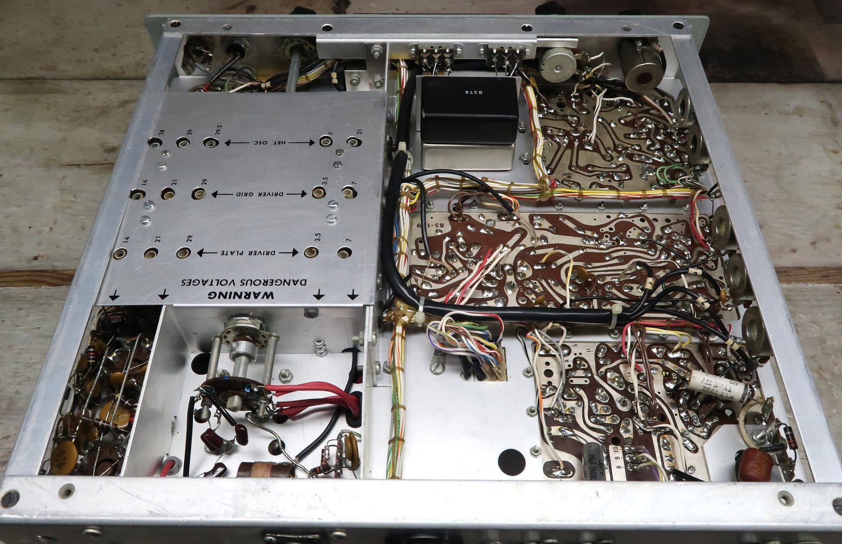
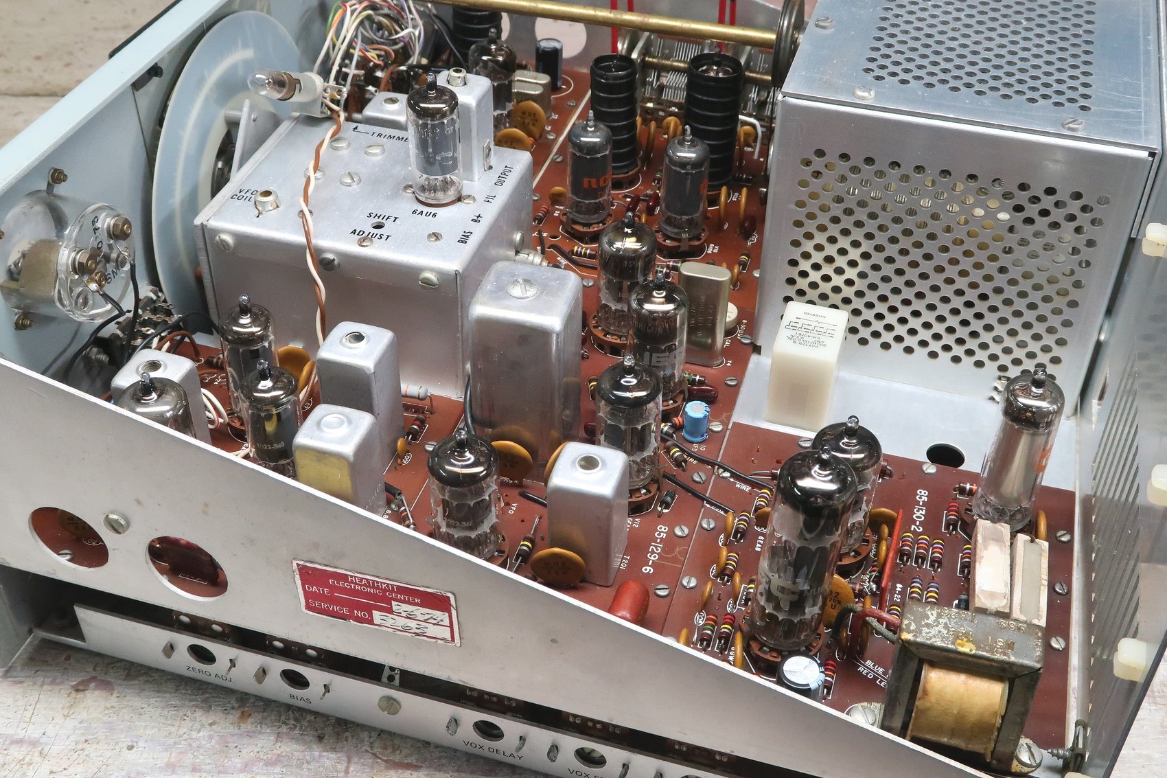
Buyers of second-hand HW-101s are repeatedly advised to look under the covers before buying, because build quality varies enormously — the rig was assembled by thousands of different people, a handful of whom were not ready for it. Practical Wireless’s advice in 2007 was blunt on the point: very few were supplied factory-assembled, so what is inside any given example is the work of one unknown amateur with one unknown soldering iron.
Sources
- Heathkit Assembly Manual for the HW-101 SSB Transceiver, part 595-1277-18 (Heath Company, 1970). Internet Archive
- Heathkit Christmas 1975 catalogue, p. 91, for the “Switch-Boards” selling point. World Radio History
- Cadman, Phil (G4JCP). “It’s a Classic! The Heathkit HW101.” Practical Wireless, November 2007, on buying a second-hand example. Scan
- Harris, Bill. “The Heathkit HW-101” — photographs of a built and restored example. Link
- The Heath manual method in general is covered in volume 8 of the site history dive.
Comments (0)