HW-101 Transceiver · Volume 6
Reference
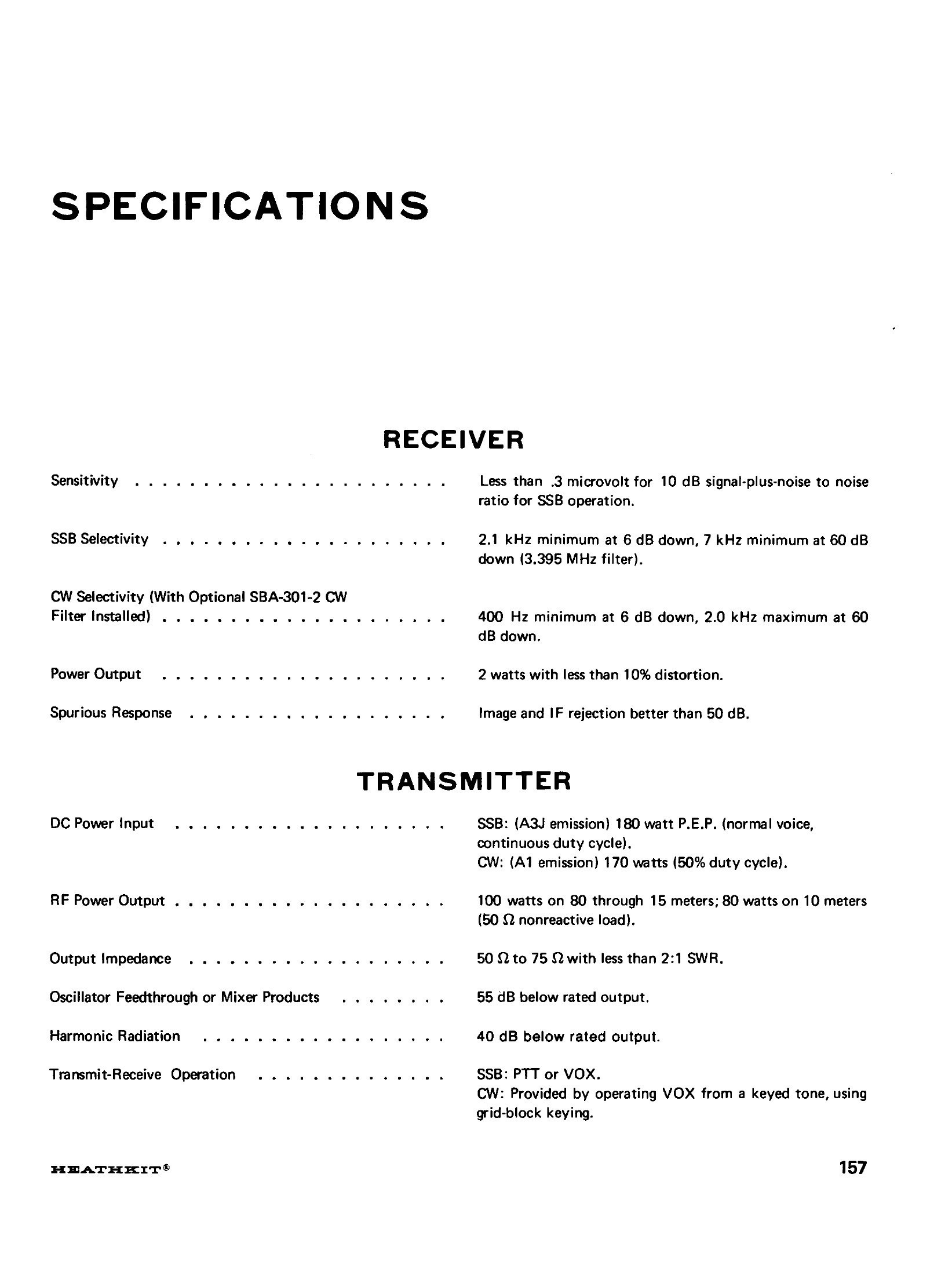
Everything in this volume comes from the HW-101 assembly manual, from Heath’s own catalogues, or from the service bulletins, and each table says which. Where the manual and a catalogue disagree — and on three points they do — both figures are given.
6.1 Full specification
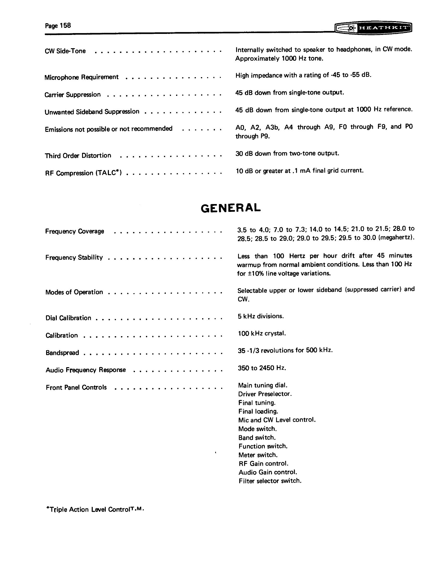
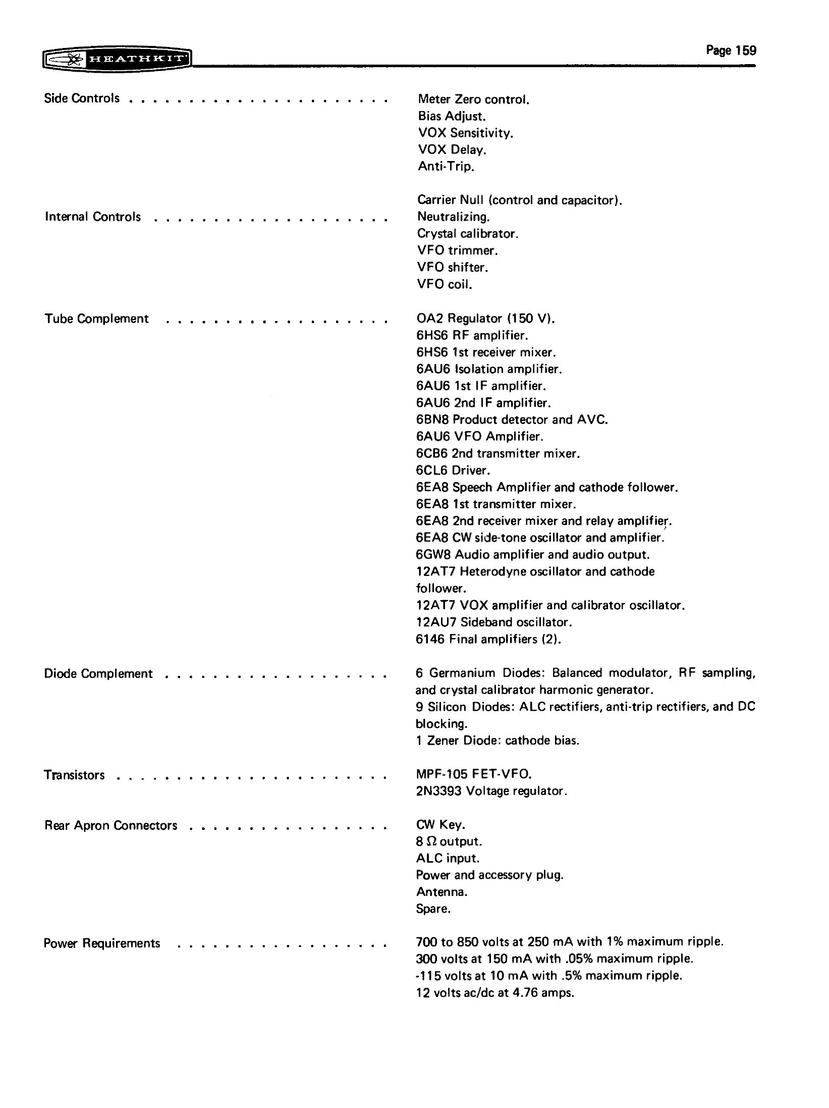
As printed in the assembly manual, pages 157 to 160.
6.1.1 Receiver
Table 1 — Receiver
| Sensitivity | Less than 0.3 µV for 10 dB signal-plus-noise to noise, SSB |
| SSB selectivity | 2.1 kHz minimum at 6 dB down, 7 kHz minimum at 60 dB down (3.395 MHz filter) |
| CW selectivity | With the optional SBA-301-2 filter: 400 Hz minimum at 6 dB down, 2.0 kHz maximum at 60 dB down |
| Audio power output | 2 W at less than 10 per cent distortion |
| Spurious response | Image and IF rejection better than 50 dB |
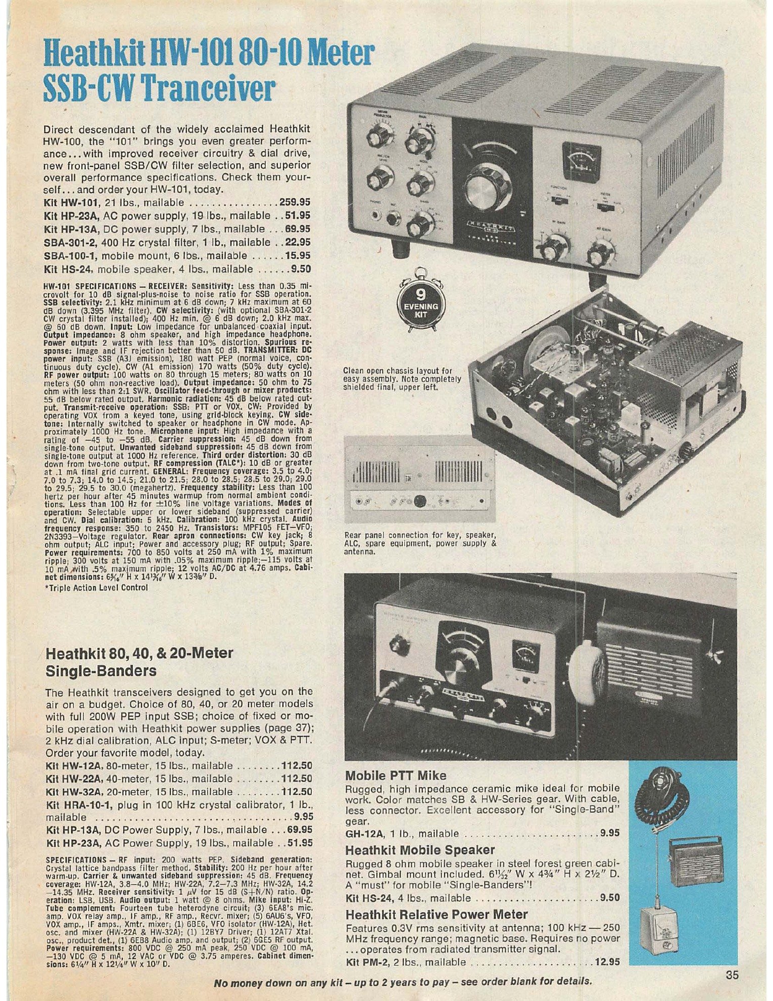
The sensitivity figure is the first of the three disagreements. The manual says 0.3 µV; every Heath catalogue from 1971 onwards says “less than 0.35 microvolt”, and the same 0.35 figure appears in the HW-101 specification block printed in those catalogues. The difference is immaterial in use but worth knowing when comparing sources.
6.1.2 Transmitter
Table 2 — Transmitter
| DC power input | SSB (A3J emission): 180 W PEP, normal voice, continuous duty cycle. CW (A1 emission): 170 W at 50 per cent duty cycle |
| RF power output | 100 W on 80 through 15 metres; 80 W on 10 metres, into a 50 Ω non-reactive load |
| Output impedance | 50 to 75 Ω at less than 2:1 SWR |
| Oscillator feedthrough or mixer products | 55 dB below rated output |
| Harmonic radiation | 40 dB below rated output (catalogues from 1971 to 1980 say 45 dB; the Winter 1981–82 catalogue says 40 dB) |
| Transmit-receive | SSB: PTT or VOX. CW: VOX operated from a keyed tone, grid-block keying |
| CW sidetone | Approximately 1000 Hz, switched internally to speaker or headphones |
| Microphone | High impedance, −45 to −55 dB |
| Carrier suppression | 45 dB below single-tone output |
| Unwanted sideband suppression | 45 dB below single-tone output at 1000 Hz reference |
| Third-order distortion | 30 dB below two-tone output |
| RF compression (TALC) | 10 dB or greater at 0.1 mA final grid current |
| Emissions not possible or not recommended | A0, A2, A3b, A4 through A9, F0 through F9, P0 through P9 |
6.1.3 General
Table 3 — General
| Frequency coverage | 3.5–4.0; 7.0–7.3; 14.0–14.5; 21.0–21.5; 28.0–28.5; 28.5–29.0; 29.0–29.5; 29.5–30.0 MHz |
| Frequency stability | Less than 100 Hz per hour after 45 minutes’ warm-up; less than 100 Hz for ±10 per cent line variation |
| Modes | Selectable upper or lower sideband, suppressed carrier, and CW |
| Dial calibration | 5 kHz divisions |
| Calibration | 100 kHz crystal |
| Bandspread | 35⅓ revolutions for 500 kHz |
| Audio frequency response | 350 to 2450 Hz |
| Cabinet dimensions | 14-13/16 in wide × 6-5/16 in high × 13-3/8 in deep |
| Net weight | 17½ lb |
| Power required | 700–850 V at 250 mA (1 per cent maximum ripple); 300 V at 150 mA (0.05 per cent); −115 V at 10 mA (0.5 per cent); 12 V AC or DC at 4.76 A |
The second disagreement is the heater current. The manual specifies 12 volts at 4.76 amperes; catalogues from about 1980 onwards print 5.76 amperes in the same line of the same specification block. No circuit change corresponding to a one-amp increase has been found, and the later figure is most likely a typesetting error carried forward from catalogue to catalogue.
The dial is the third place where sources differ, though only in the way the same mechanism is described. The manual specifies a bandspread of 35⅓ revolutions per 500 kHz; the catalogue copy from 1971 onwards advertises “36-to-1 knob to dial ratio in a new ball bearing drive mechanism” delivering “34 smooth revolutions per 500 kHz band segment”.
6.2 Tube complement
Twenty envelopes. Transcribed from the manual’s specification page rather than from OCR, because the tube list is exactly the kind of table optical recognition mangles.
Table 4 — Tube complement
| Type | Function | Designator |
|---|---|---|
| OA2 | Regulator, 150 V | V18 |
| 6HS6 | RF amplifier | V10 |
| 6HS6 | First receiver mixer | V11 |
| 6AU6 | Isolation amplifier | V2 |
| 6AU6 | First IF amplifier | V3 |
| 6AU6 | Second IF amplifier | V4 |
| 6BN8 | Product detector and AVC | V13 |
| 6AU6 | VFO amplifier | V20 |
| 6CB6 | Second transmitter mixer | V6 |
| 6CL6 | Driver | V7 |
| 6EA8 | Speech amplifier and cathode follower | V1 |
| 6EA8 | First transmitter mixer | V5 |
| 6EA8 | Second receiver mixer and relay amplifier | V12 |
| 6EA8 | CW sidetone oscillator and amplifier | V15 |
| 6GW8 | Audio amplifier and audio output | V14 |
| 12AT7 | Heterodyne oscillator and cathode follower | V19 |
| 12AT7 | VOX amplifier and calibrator oscillator | V17 |
| 12AU7 | Sideband (carrier) oscillator | V16 |
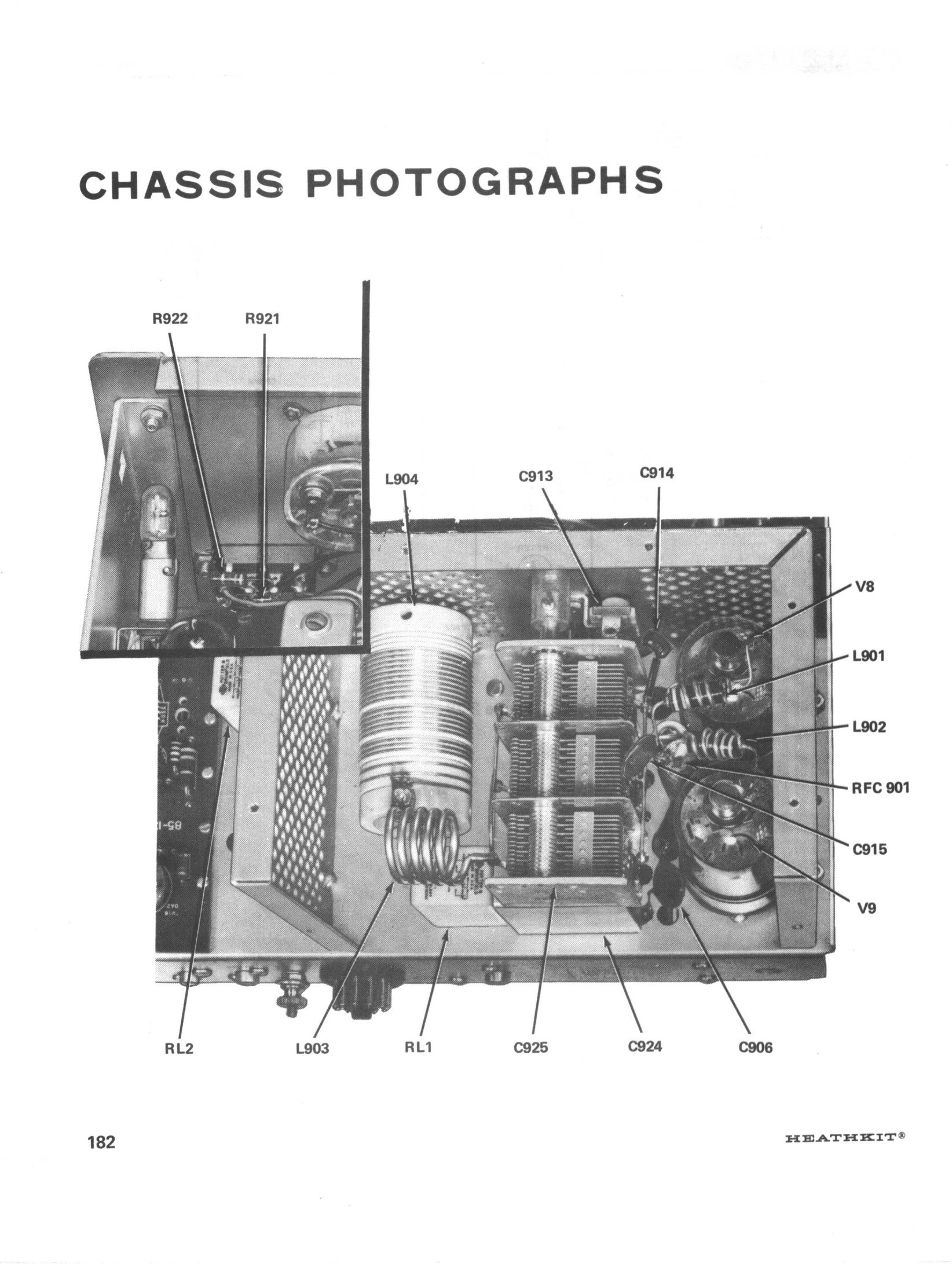
| 6146 | Final amplifier | V8 |
| 6146 | Final amplifier | V9 |
Final amplifier substitution. The manual states that 6146 and 6146A “may be directly interchanged”. Service bulletin HW-101-18 of 20 January 1978 adds that the 6146B may cause the final plate RF choke to overheat or make the set difficult to neutralise on 10 and 15 metres, that 6146A tubes should be fitted instead, and that “the 6146B tubes should not be used as a replacement”. Heath fitted a rear-panel label to later production saying so.
6.2.1 Semiconductors
Table 5 — Semiconductors
| Device | Function |
|---|---|
| MPF-105 | VFO oscillator (field-effect transistor) |
| 2N3393 | Voltage regulator, used as a zener (base-emitter junction only) |
| 6 germanium diodes | Balanced modulator, RF sampling, calibrator harmonic generator |
| 9 silicon diodes | ALC rectifiers, anti-trip rectifiers, DC blocking |
| 1 zener diode | Cathode bias (relay amplifier) |
6.3 Frequency data
Table 6 — Frequency data
| Band (MHz) | Heterodyne crystal (MHz) | First IF (MHz) | VFO (MHz) | Second IF (MHz) |
|---|---|---|---|---|
| 3.5–4.0 | 12.395 | 8.5 | 5.105 | 3.395 |
| 7.0–7.3 | 15.895 | 8.695 | 5.3 | 3.395 |
| 14.0–14.5 | 22.895 | 8.695 | 5.3 | 3.395 |
| 21.0–21.5 | 29.895 | 8.595 | 5.2 | 3.395 |
| 28.0–28.5 | 36.895 | 8.795 | 5.4 | 3.395 |
| 28.5–29.0 | 37.395 | 8.695 | 5.3 | 3.395 |
| 29.0–29.5 | 37.895 | 8.695 | 5.3 | 3.395 |
| 29.5–30.0 | 38.395 | 8.795 | 5.4 | 3.395 |
Carrier crystals: Y1 at 3396.4 kHz (USB), Y2 at 3393.6 kHz (LSB), Y3 at 3395.4 kHz (CW). Crystal filter FL1: centre 3395 kHz, 3393.95 to 3396.05 kHz at the 6 dB points. Calibrator crystal: 100 kHz.
6.4 Controls and connections
Front panel: main tuning dial; DRIVER PRESELECTOR; FINAL tuning; FINAL loading; MIC and CW LEVEL; MODE switch; BAND switch; FUNCTION switch; METER switch; RF GAIN; AUDIO GAIN; FILTER selector switch.
Side of chassis: METER ZERO; BIAS ADJUST; VOX SENSITIVITY; VOX DELAY; ANTI-TRIP.
Internal: CARRIER NULL (control and capacitor); NEUTRALIZING; crystal calibrator trimmer; VFO trimmer; VFO shifter; VFO coil.
Rear apron: CW key jack; 8 Ω speaker output; ALC input; eleven-pin power and accessory plug; antenna; one spare socket.
6.5 Heath accessories
Prices are the kit prices printed in the catalogue named; all are from World Radio History scans.
Table 7 — Heath accessories
| Model | What it is | Price and catalogue |
|---|---|---|
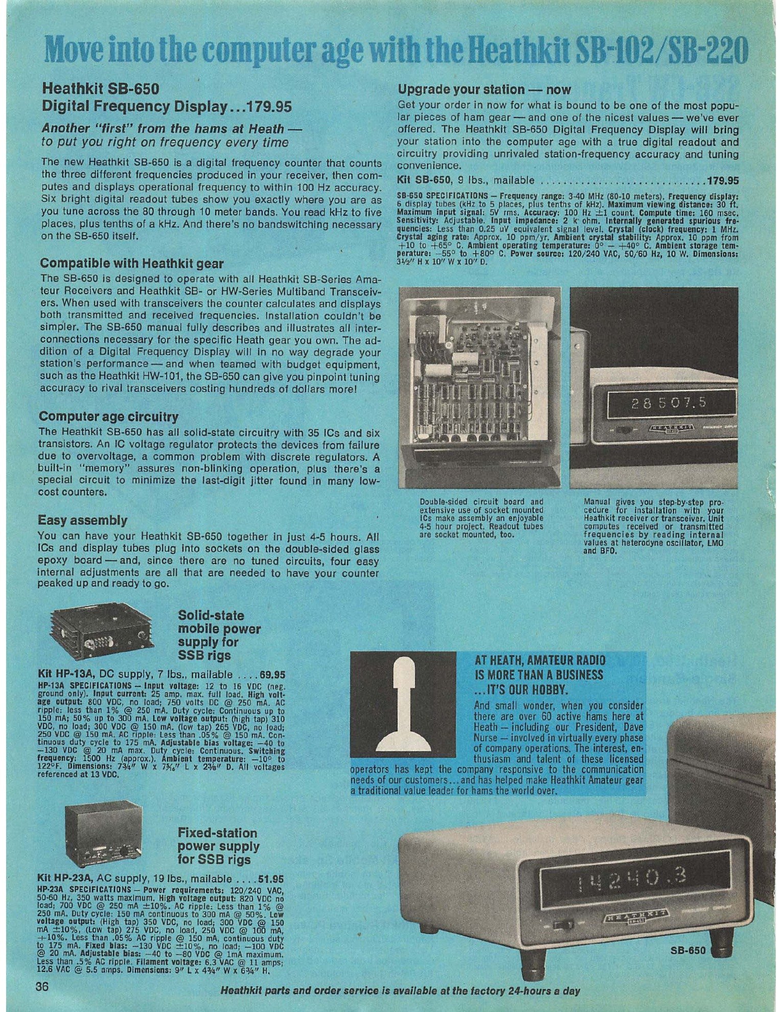
| HP-23, HP-23A, HP-23B, HP-23C | AC power supply, 120/240 V from the -A onwards. Fixed-station supply for the whole SB and HW line | $51.95 (HP-23A, 810/72) |
| PS-23 | The HP-23C renamed, from about 1980 | $79.95 (Winter 1981–82) |
| HP-13, HP-13A, HP-13B | Solid-state mobile DC supply, 12 V input | $69.95 (HP-13A, 810/72) |
| SB-600 | Matching speaker cabinet; has space and mounting holes inside for an HP-23 | $19.95 (1971 catalogue) |
| HS-1661 | Later matching speaker, 5 × 7 in oval, for the HW-101 and HR-1680 | $29.95 (Winter 1981–82); $34.95 (Winter 1983) |
| HS-24 | Mobile speaker | $8.95 (810/72) |
| SBA-100-1 | Mobile mounting bracket; the rig lifts in and out | $17.95 (810/72) |
| SBA-301-2 | 400 Hz CW crystal filter, front-panel switched | $21.95 (810/72); $29.95 (Christmas 1975); $39.95 (Winter 1983) |
| SB-650 | Digital frequency display, six Nixie tubes, 100 Hz resolution, works with SB and HW multiband transceivers | $179.95 (catalogue 810/73, 1973) |
| SB-200, SB-201, SB-220, SB-221 | Linear amplifiers; the HW-101’s 100 W output is exactly the drive an SB-200 wants | $220.00 (SB-200, 810/72) |
| HDP-21, HDP-121 | Matching desk microphone | — |
| HN-31 “Cantenna” | 50 Ω dummy load, the one Heath used to prepare the HW-101’s own specifications | — |
The HP-23 family’s differences matter when buying one. The original HP-23 of 1963 is 120 V only and has an adjustable bias supply; the HP-23A of 1968 added dual primaries for 120 or 240 V and a circuit breaker; the HP-23B of 1973 dropped the adjustable bias and the filament centre tap and gained a three-wire earthed mains lead; the HP-23C of 1978 dropped the front-panel power switch, leaving the supply controlled entirely by the transceiver; and the PS-23 is the HP-23C under a new name. All of them will run an HW-101 (Eckweiler, Heathkit of the Month #26).
6.6 Manuals and documents
Assembly manual, HW-101 SSB Transceiver — Heath part number 595-1277-18.
- Publication year: copyright 1970 (title page: “Copyright © 1970, Heath Company, Benton Harbor, Michigan 49022”).
- Copyright notice seen: yes, on the title page.
- Renewal search: not done.
- Hosting decision under the project rule (host only titles likely to be public domain — pre-1964 without renewal, or published without notice): link only, do not host. The title is dated 1970 and carries a notice.
- The scans found are all of the same edition, 595-1277-18. Late printings carry a revised warranty page mentioning computer peripherals and software, so the same part number was reprinted well into the 1980s.
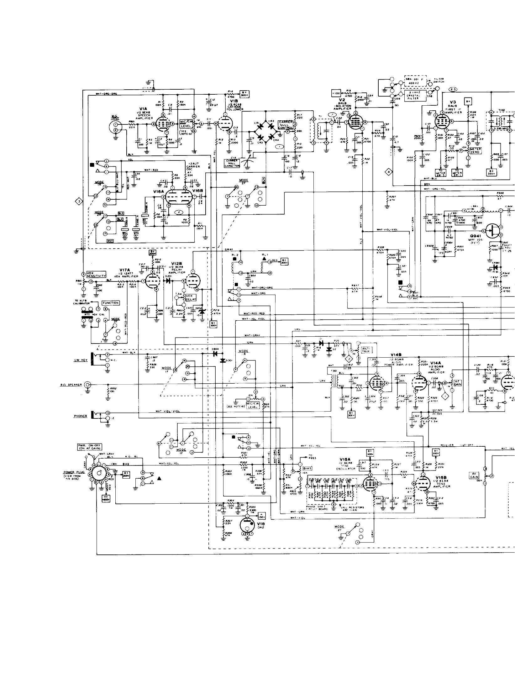
- The fold-out schematic inside the manual carries its own part number, 595-1277-17.
Table 8 — Manuals and documents
| Where | Notes |
|---|---|
| archive.org/details/HeathkitHw-101 | 245 pages, 28 MB, the cleanest of the scans; a text-layer PDF and OCR text are also present |
| archive.org/details/OCRHeathkitHw101 | The same manual in the heathkitmanuals collection, 13 MB |
| archive.org/details/HeathkitHW101SSBTransceiver1970WW | A third scan of the same edition, 18 MB |
| archive.org/details/Heathkit_HW-101_SSB_Transciever | A short extract, not the full manual |
| archive.org/details/Heathkit_HW-101_SSB_Transciever_schematic_only | The schematic alone |
| Frostburg (Bill Harris) | The full manual, the HP-23 manual, the service bulletins, the 2007 Practical Wireless review and tube data sheets, all as PDFs |
| vintage-radio.info | Heathkit schematic and manual archive, rate-limited to ten files per fifteen minutes |
Service bulletins. Heath issued bulletins for the model from HW-101-1 (11 February 1971, VFO drift) to HW-101-55 (19 November 1979, AVC decay). A transcript of the series — noting that the 1977 microfiche was never received, so the run is incomplete — is hosted at Frostburg. Many HW-101 bulletins simply point at the corresponding HW-100, SB-100 or SB-102 bulletin, which is a useful reminder of how closely related the four rigs are.
Accessory manuals. The HP-23 power supply manual is at Frostburg (21 pages). The same hosting rule applies to it and to the SB-650 and SBA-301-2 documentation: 1960s and 1970s Heath publications carrying a copyright notice are linked here, not hosted.
Catalogues. All the Heath catalogues cited in this dive are on World Radio History’s Heathkit catalogue index. Catalogues and flyers count as advertising under the project’s rule, and are handled the same way as the manuals until a renewal check is done.
6.7 Related Heath equipment
Table 9 — Related Heath equipment
| Model | Relationship |
|---|---|
| HW-12, HW-22, HW-32 (and -A versions) | The single-band “Hard Working” transceivers that established the HW line and the external-supply pattern |
| SB-100 (1965), SB-101 (1967), SB-102 (1970) | The SB transceivers the HW rigs were cost-reduced from; the SB-102 is the HW-101’s direct sibling, with a solid-state LMO and rotary switches in place of the HW’s two slide switches |
| HW-100 (1968) | The HW-101’s immediate predecessor: Harmonic Drive dial, one filter position, 0.5 µV sensitivity |
| SB-110, SB-110A | The six-metre member of the same family |
| SB-301, SB-401 | The separate receiver and transmitter of the same generation |
| SB-104, SB-104A (1974, 1977) | The solid-state transceiver that was meant to replace the tube rigs; the HW-101 outlived both |
| HW-104 (1975) | The HW-line version of the SB-104, described in the Christmas 1975 catalogue as bringing “the high value concept of the HW-101” to a solid-state design |
| HW-5400 (1983) | The synthesised transceiver that replaced the HW-101 in the catalogue |
Further reading
- Heathkit Assembly Manual for the HW-101 SSB Transceiver, 595-1277-18 (Heath Company, 1970). The primary source for everything technical in this dive. Internet Archive
- Cadman, Phil (G4JCP). “It’s a Classic! The Heathkit HW101.” Practical Wireless, November 2007, pp. 22, 26–27. The best short retrospective: block diagram, buying advice, and a British perspective on an American rig. Scan
- Harris, Bill. “The Heathkit HW-101.” A complete documented restoration with photographs of every board, every alignment point and every repair. Link
- Eckweiler, Bob (AF6C). Heathkit of the Month: #26 on the HP-23 family, #40 on the HP-13 mobile supplies, #30 on the SB line. The reference works for the accessories.
- Penson, Chuck (WA7ZZE). Heathkit: A Guide to the Amateur Radio Products (Electric Radio Press). The standard collector’s reference on Heath ham gear; not consulted directly for this dive. His anniversary article is online at the Heathkit Virtual Museum.
- Nostalgic Kits Central, Heathkit alphabetic equipment matrix, for model years across the whole range. Link
- The Heath Company’s own history is the subject of the site history dive.
Sources
- Heathkit Assembly Manual for the HW-101 SSB Transceiver, 595-1277-18 (Heath Company, 1970), specification pages 157–160 and the parts identification tables. Internet Archive
- Heath Company, HW-101 service bulletins. Transcript
- Heathkit catalogues: 800/13, 1971 · 810/72 · 810/73 · Christmas 1975 · 1971 general catalogue · Winter 1981–82 · Winter 1983
- Eckweiler, Bob (AF6C). Heathkit of the Month #26, #30 and #40. OCARC index
- Cadman, Phil (G4JCP). Practical Wireless, November 2007. Scan
Comments (0)