HW-101 Transceiver · Volume 5
Restoration and Common Faults
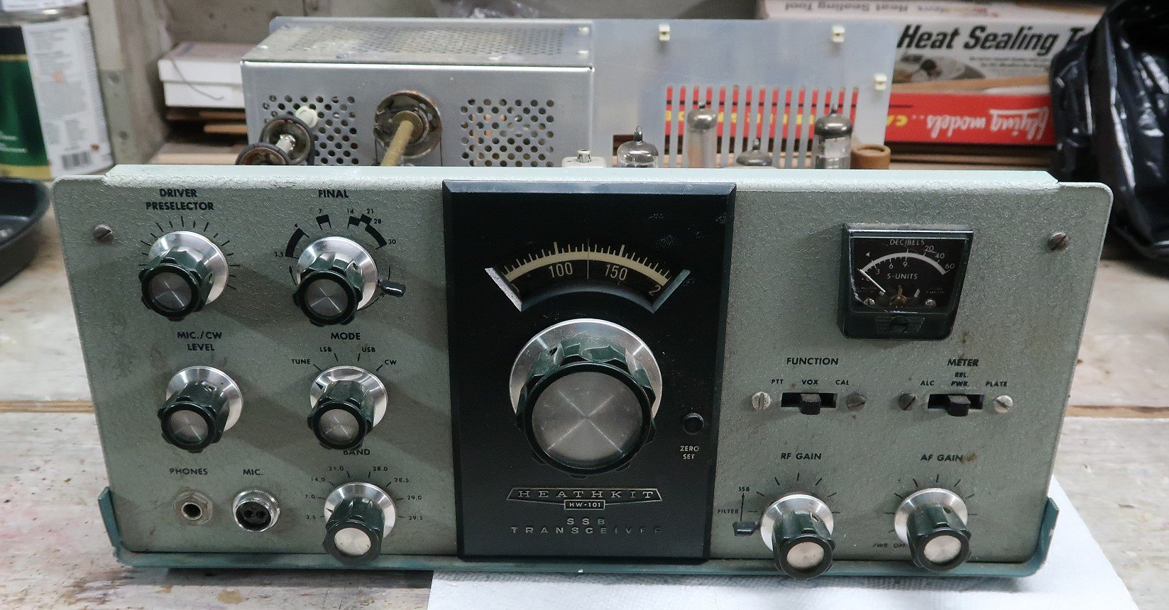
An HW-101 bought today is between forty-three and fifty-six years old, was assembled by an unknown person of unknown skill, has probably been modified at least once, and contains a power supply capable of killing whoever opens it carelessly. It is also one of the most restorable pieces of amateur equipment ever made, because everything in it is a discrete part in an accessible place, the manual documents every voltage and resistance in the set, and Heath itself published a run of service bulletins over nine years — numbered up to HW-101-55 — that name the faults before they are found.
5.1 Safety, first and repeatedly
The transceiver itself carries 700 to 850 volts on the final amplifier plates and 300 volts on the rest of the B+ line. The power supply that produces those voltages is a pair of voltage doublers feeding large electrolytic capacitors, and those capacitors hold their charge after the mains is disconnected. The manual’s own instruction is the right habit: switch off, unplug the cable, and short the red B+ wires to the chassis with a screwdriver blade before touching anything.
Three further rules are worth stating plainly because the rig invites breaking them. Do not work inside a transceiver whose power supply is still connected, even switched off. Do not defeat the interlocks or work with the final cage open while transmitting. And treat the HP-23’s own cabinet as live inside, because with its lid off the doubler capacitors are exposed at full voltage.
5.2 Buying and first assessment
The advice repeated by everyone who has restored one is the same: look under the covers before parting with money. Very few HW-101s left Benton Harbor assembled, so the quality inside any given example is the quality of one amateur’s soldering. Practical Wireless put the point bluntly in 2007 — build quality “can vary enormously” — and added that modifications should be examined rather than feared, since almost every Heathkit rig was modified by its owner at some point.
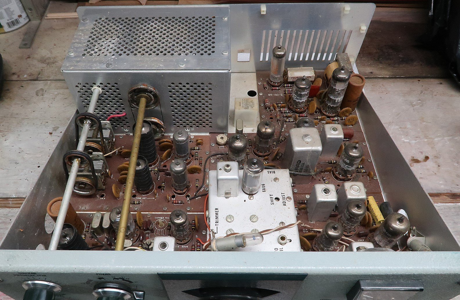
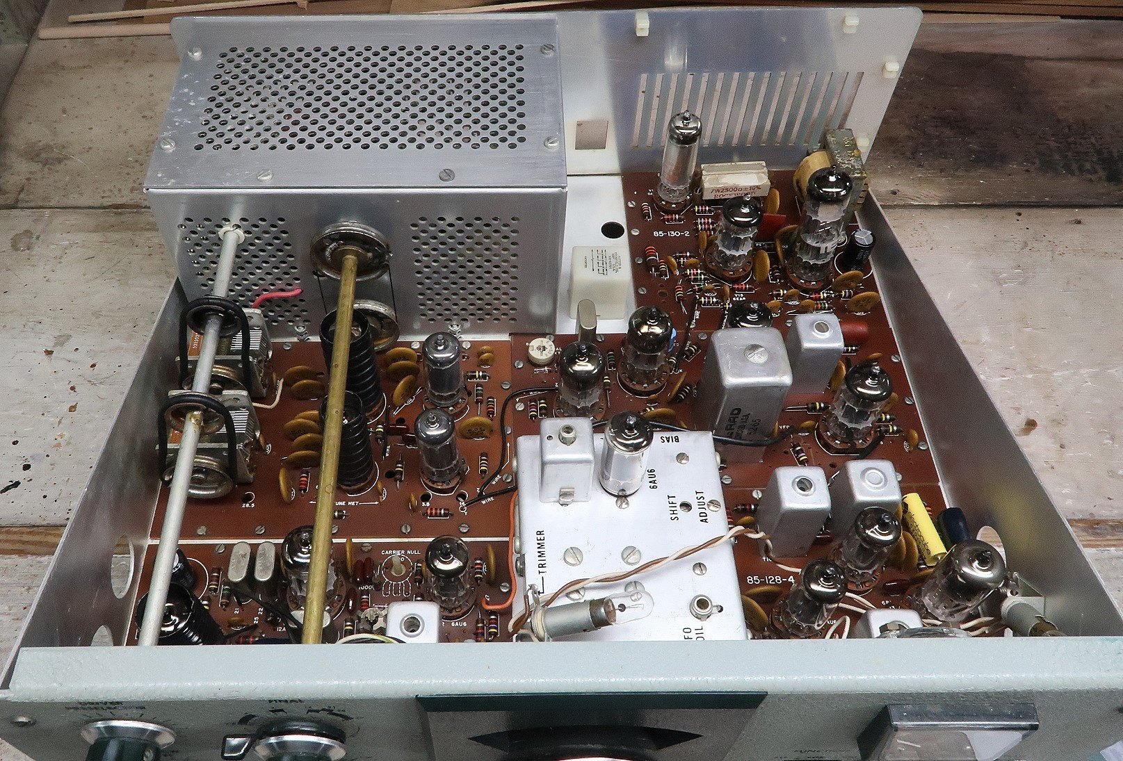
What to look for, in order: the state of the soldering on the boards and the harness; whether the final cage and coil covers are present; whether the crystal filter and the optional CW filter are fitted; whether the phono antenna socket has been replaced with an SO-239; and whether the preselector drive belts have turned to tar. A set that has been stored dry and not butchered is a weekend’s work; a set that has been “improved” by three previous owners can be a month’s.
5.3 Bringing one up
The sequence that experienced restorers follow is conservative and worth following in order.
Document before disturbing. Pull the tubes and write down which type came out of which socket. The HW-101 uses four 6AU6s and four 6EA8s in different positions, and a tube that has aged into a particular circuit is best returned to it.
Inspect and clean. Vacuum, compressed air, and a careful look for bad joints, scorched resistors and evidence of past repairs. Stiff controls and switches respond to a contact cleaner; the band switch and the filter slide switch both handle signals in both directions, and a Heath service bulletin of 1979 warns specifically that dirt on the SSB/CW filter slide switch shows up as low transmitter output and low receiver sensitivity at the same time.
Test the tubes, but do not trust the tester. A tube tester measures emission or gain under a standard condition; several of the faults Heath documented are leakage faults that a tester will pass. The two worth knowing: leakage in the 6HS6s at V10 or V11, which shows up as poor AGC action, fast S-meter decay and poor sensitivity with the RF gain fully clockwise, usually only after an hour of warm-up, and is diagnosed by finding a positive volt or more on pin 1; and a defective V12 that leaves the relays energised for thirty to forty seconds after a transmission because a positive voltage appears on its control grid.
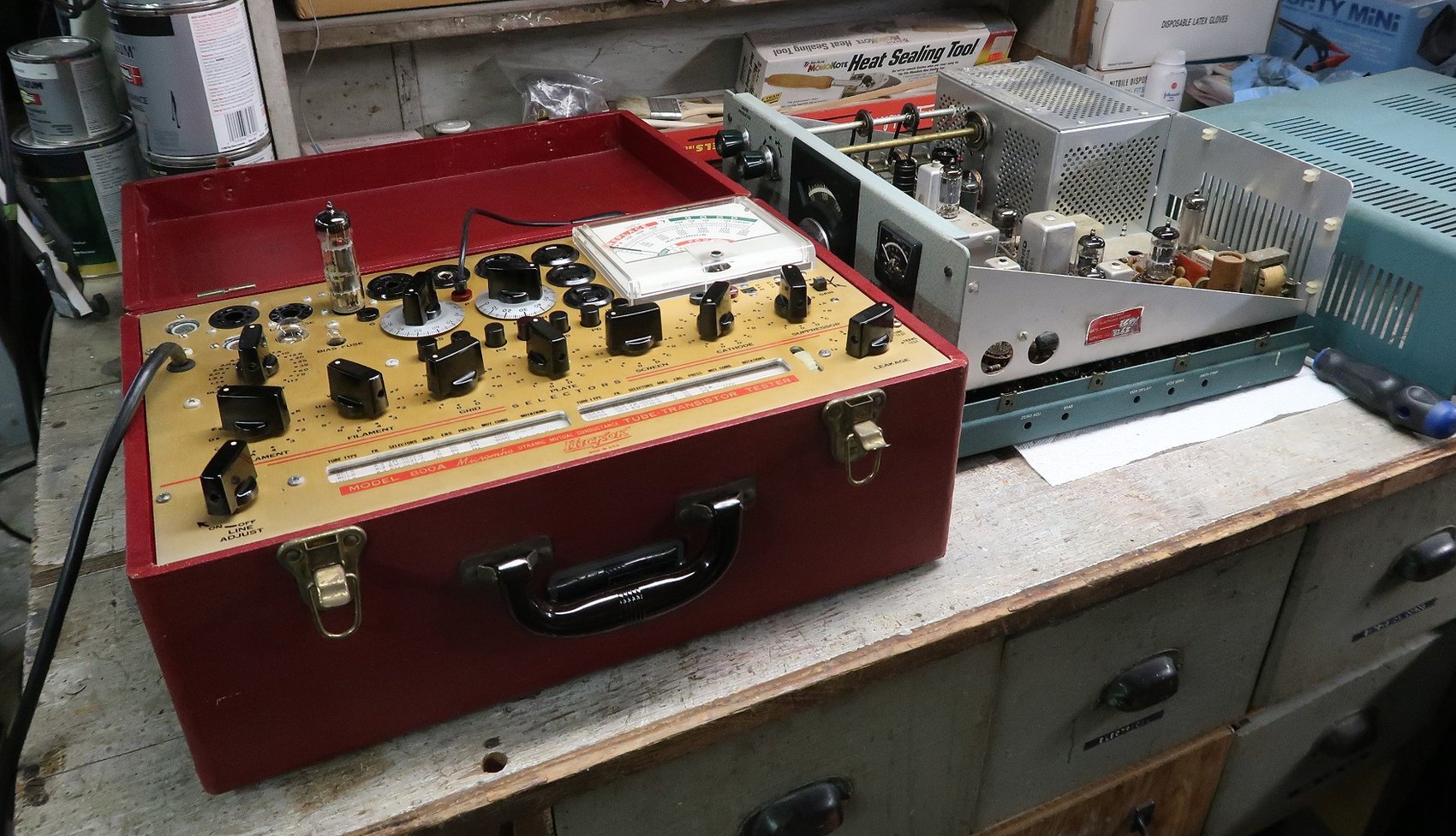
Power up slowly. A variac, brought up gradually with the set watched and sniffed at each step, is the standard approach; a series lamp limiter serves the same purpose for a first power-up on the supply alone. The point is to re-form electrolytics that have sat unpowered for decades rather than to present them with full voltage at once.
Then replace the electrolytics anyway. There are only a handful in the transceiver — the cathode bypasses at C2 and C212, the 20 µF 350 V decoupling capacitors C12 and C304, and the 10 µF 150 V bias filter C906 — and they are cheap. The argument for replacing capacitors that test acceptable is that a dried-out electrolytic can pass a bench test and then fail warm, and the cost of the failure is not confined to the capacitor.
5.4 What actually goes wrong
Heath’s own service bulletins, issued from February 1971 to November 1979, are the best fault catalogue in existence for this rig, because they were written by the people answering the telephone. The recurring themes are these.
5.4.1 The 6146B trap
The single most important thing to know about maintaining an HW-101 is which final tubes to fit. The assembly manual says that “tube types 6146 and 6146A may be directly interchanged”. It does not mention the 6146B, because in 1970 the 6146B was not yet in wide circulation. By January 1978 Heath had seen enough of it to issue bulletin HW-101-18, titled “RF choke in final plate circuit overheats or difficult to neutralize on 10 meter & 15 meter bands”:
6146B tubes in the final amplifier may be causing this problem. To correct, replace with 6146A tubes.
The bulletin goes on to say that a label would be fitted to the back panel of the HW-101 recommending 6146A tubes only, and that “the 6146B tubes should not be used as a replacement”. The 6146B has different internal capacitances; in a circuit neutralised for the earlier tube it can be impossible to neutralise on the higher bands, and the plate choke pays for the resulting circulating current. This is the one substitution that must not be made casually, and it is also one that a seller may have made years ago without recording it.
5.4.2 Drift, warble and erratic tuning: the VFO
The first bulletin Heath ever issued for the model, HW-101-1 of 11 February 1971, concerns VFO drift and specifies a replacement coil — part 40-1976 in place of 40-810 — “whenever a unit displays excessive drift”, a change made permanent in later production. Three more followed over the years, and together they read as a list of everything that can go wrong with an oscillator built on a chassis:
- Repeated heterodyne oscillator tube failure, and inadequate shift between sidebands (HW-101-2, September 1972): two changes in one bulletin — R212 from 220 Ω to 330 Ω, and, for the shift range, the FET source resistor R947 from 470 Ω to 1 kΩ.
- Intermittent frequency shift (HW-101-19, 1978): the VFO trimmers tend to align near minimum capacitance, where the screw head is not pressing firmly on the spring plates. Changing C947 from 56 to 47 pF moves the trimmers to a tighter part of their range.
- Erratic tuning (HW-101-27, 1978): an intermittent electrical contact in the vernier drive changes the ground path from the tuning capacitor frame, which changes the capacitance. The cure is to solder a heavy wire or braid from the stop stud to a solder lug under the nearest mounting screw.
- “Warble” when the chassis is tapped (HW-101-42, 1978): the leads of C946 and C953 are long enough to let the capacitors vibrate. Glue the top of C946 to the VFO chassis wall.
5.4.3 Drifting resistors
Carbon composition resistors absorb moisture and rise in value with age, and the HW-101 is full of them. Practical Wireless named them as the fault most often met in the rig, and one restoration documents a spectacular case: a receiver markedly less sensitive on USB and CW than on LSB, traced to the carrier oscillator’s plate resistors — R6 had drifted from 33 kΩ to 330 kΩ, a factor of ten, and R7 from 33 kΩ to 42 kΩ. Replacing both restored the missing sensitivity.
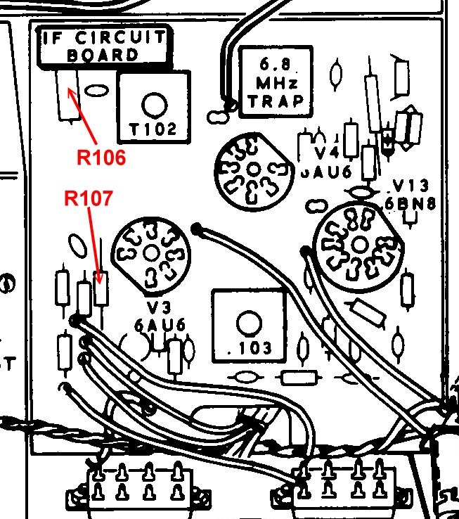
Two other resistors have their own bulletins. R107, the 100 kΩ half-watt resistor in the S-meter divider, was raised to a 1-watt part in March 1976 to stop the meter drifting as the string warmed (HW-101-10), and later advice pairs it with a 2-watt, preferably wirewound, replacement for the 22 kΩ R106. R117 in the AVC circuit goes open and produces fast S-meter decay (HW-101-55, November 1979), with a warning to dress the replacement away from the protruding AVC wire ends so that they cannot pierce its coating.
5.4.4 Crystals
Two crystal faults recur. A dead band is usually a dead heterodyne crystal — but the correct order of diagnosis matters, and the temptation to swap first is worth resisting. Check the connections to the crystal and its coil through the band switch; try readjusting the coil, because the crystal may be oscillating and simply not being resonated; only then replace. One documented case of a dead 29.5 MHz band ended with a crystal from a scrapped set, which worked only after L608 was readjusted for it. SB-102 crystals are the same parts.
The other is the 100 kHz calibrator crystal (HW-101-25, June 1978): strong signals appearing at points other than 100 kHz multiples, diagnosed by looking at the calibrator output on an oscilloscope, where a choppy or uneven upper half of the sine wave indicates the crystal itself. A noisy calibrator crystal can also misbehave through the B+ line — one restoration found calibrator noise overloading the heterodyne oscillator and the anti-trip circuit, so that the receiver noise jumped and the rig tripped into transmit unless the anti-trip control was backed right off.
5.4.5 Relays
RL2 does all the switching except the antenna, and it is a mechanical part in a hot box. Carbon builds up at the base of the contacts and produces “chirping” audio on receive and slow recovery after a long transmission (HW-101-32, August 1978): remove the cover and clean the carbon tracks, or replace the relay. Relay chatter in VOX has its own chain of bulletins, ending with one that traces it to noise on the white-red-red wires from the mode and function switches overriding the reverse bias on D201, and prescribes replacing those two wires with shielded cable grounded near the junction of R213 and R214.
5.4.6 Pilot lamps, of all things
Bulletin HW-101-20 of February 1978 is a good illustration of how tightly everything in a tube rig is coupled. The number 44 pilot lamps fitted at the time draw 250 mA each, which unbalances the series-parallel filament string; the symptoms listed are low power output and S-meter drift. The fix is to change the lamps to type 47. An owner chasing low output through the RF chain would never think to look at the dial lamps.
5.4.7 Mechanical faults
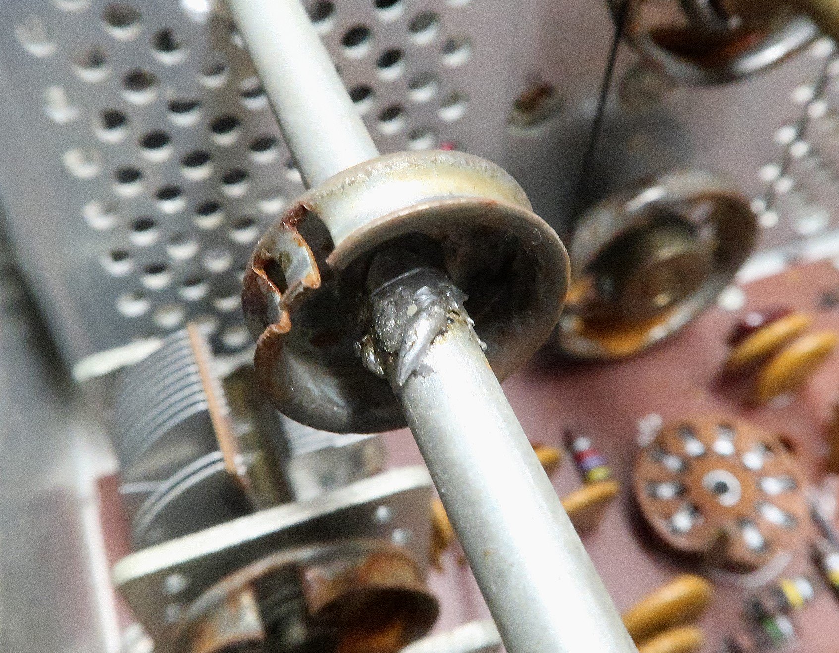
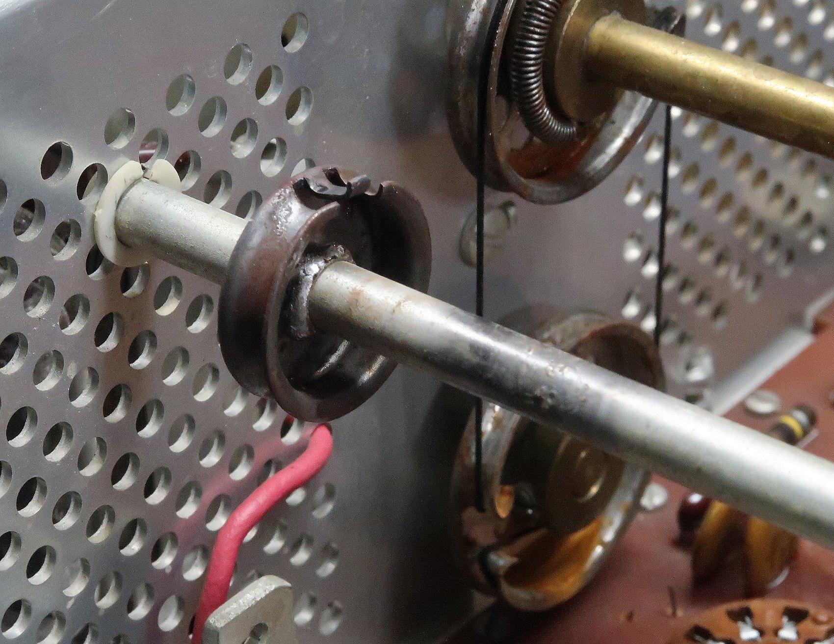
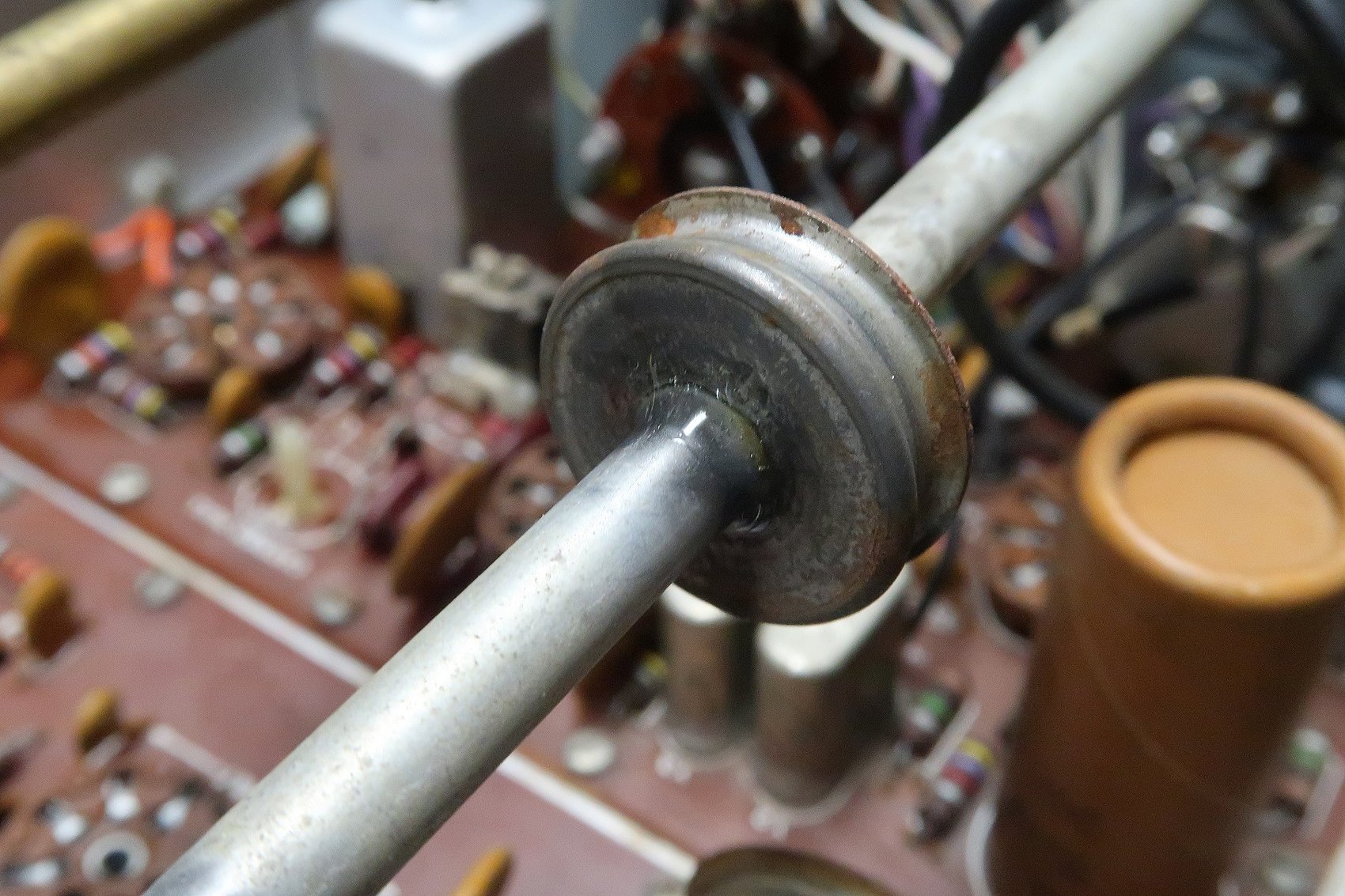
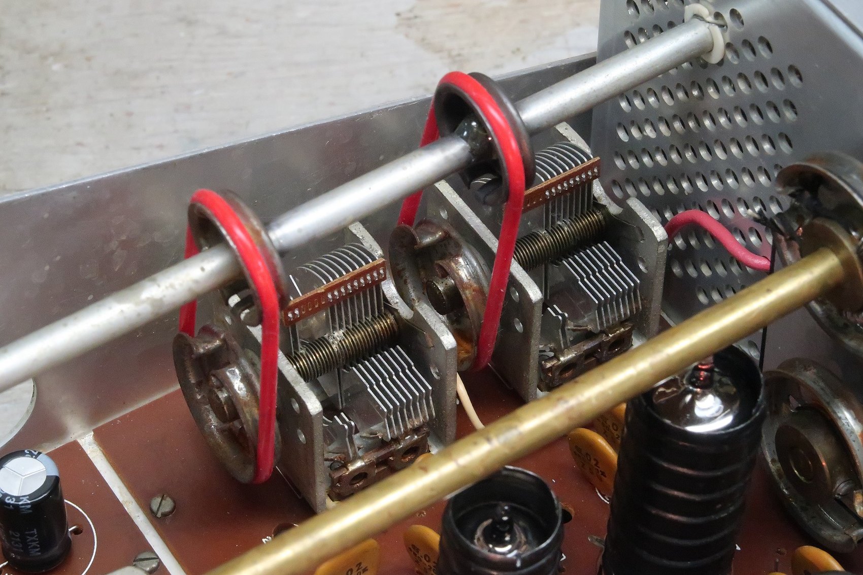
The preselector drive. The two air-variable capacitors of the driver preselector are turned by rubber belts from a drum on the control shaft. Two things fail. The belts perish, stretch and eventually go sticky; replacements are silicone belts of roughly 50 mm inside diameter, 56 mm outside and 3 mm thick, and the same belt fits the SB-100, SB-101, SB-102, HW-100 and HW-101. And the drum itself works loose, because it was soldered to the shaft by a builder whose iron could not put enough heat into a steel shaft. One documented repair grinds away the old solder, cleans the shaft and sets the drum with epoxy, adding a bead around the rim.
The carrier null control. Heath’s bulletin HW-101-3 of February 1973 records that the control at part number 10-147 was failing often enough for production to change: a fibre washer for greater clearance, and the case of the control grounded by a separate wire. The bulletin ends by asking dealers to report whether the change helped — an unusually candid piece of factory correspondence. Restorers today generally find that a failed carrier null pot has to be replaced rather than cleaned.
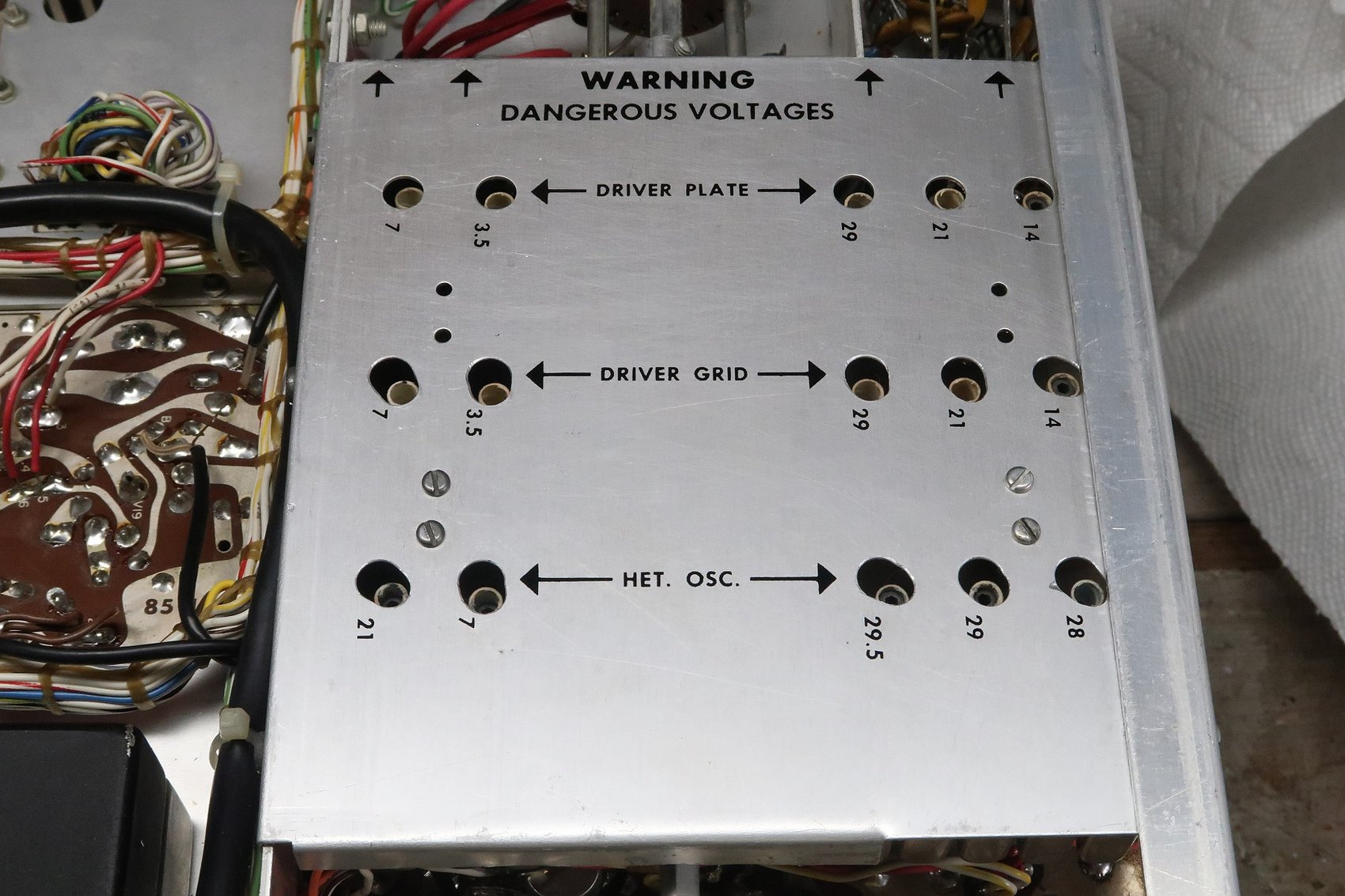
Coil covers. The driver plate, driver grid and heterodyne oscillator coil covers are supposed to be in place while their coils are adjusted, because the cover changes the tuning. On many sets the holes do not line up well enough to allow it, and the covers get left off — which means the alignment is done under the wrong conditions. Enlarging the existing holes slightly with a fine burr is preferable to drilling them out.
5.4.8 Heat
The final amplifier compartment runs hot — hot enough that Practical Wireless recommended adding forced air, noting that Heath never offered a matching fan and that the improvisation should not involve cutting holes in the cabinet. An externally mounted fan moving air across the cage extends the life of the 6146s and of everything around them, and is the single most common modern modification.
5.5 Modifications
Modifications fall into three groups, and it is worth keeping them straight when assessing a set.
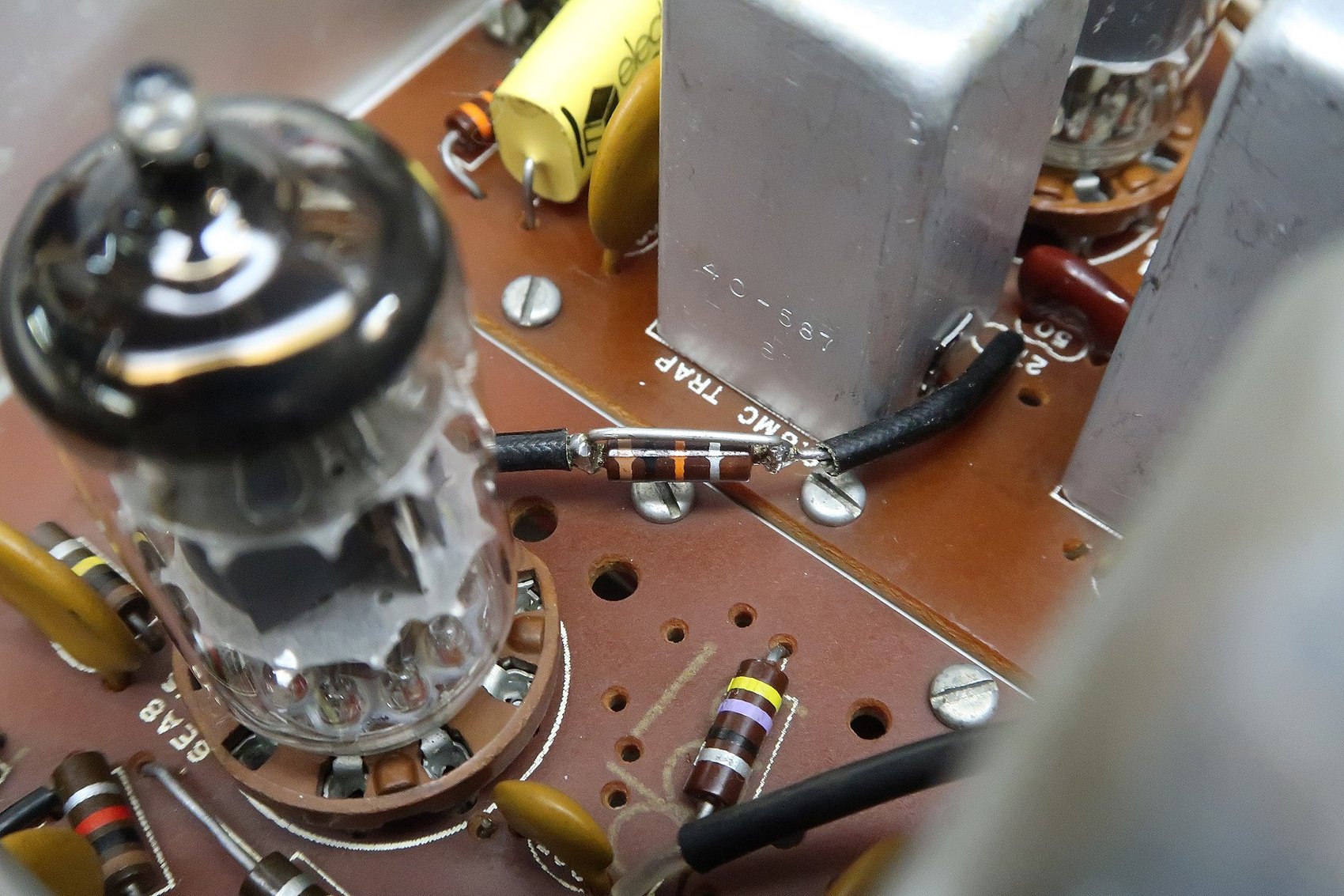
Heath’s own changes. The factory changed the design during production and told owners about it through bulletins. The commonest one visible today is resistor R202, a 10 kΩ half-watt resistor between the first IF amplifier’s output and the first transmit mixer’s grid, which early units have and later ones do not. One restorer’s solution is a good model for the genre: rather than remove the resistor, shunt it with a wire, which takes it out of circuit while leaving the evidence that this is an early set.
Period modifications published by amateurs. The best known is the addition of receiver incremental tuning, adapted from an article in QST for March 1969 and applied to the whole SB and HW family; the rig’s lack of RIT is its most-noticed omission. Others of the era address the sidetone level (Heath’s own bulletins raised R326 to 3.3 MΩ and later offered the SB-101 circuit), the ALC behaviour, IF screen voltages and the removal of birdies.
Modern practical changes. Replacing the phono antenna socket with an SO-239 is almost universal and is defensible on both electrical and mechanical grounds. Adding a low-impedance headphone jack, fitting a fan, and swapping the eleven-pin power connector for an octal are all common. None of them is reversible without leaving marks, which is the argument for documenting whatever is done and leaving the documentation with the rig.
5.6 Cosmetics
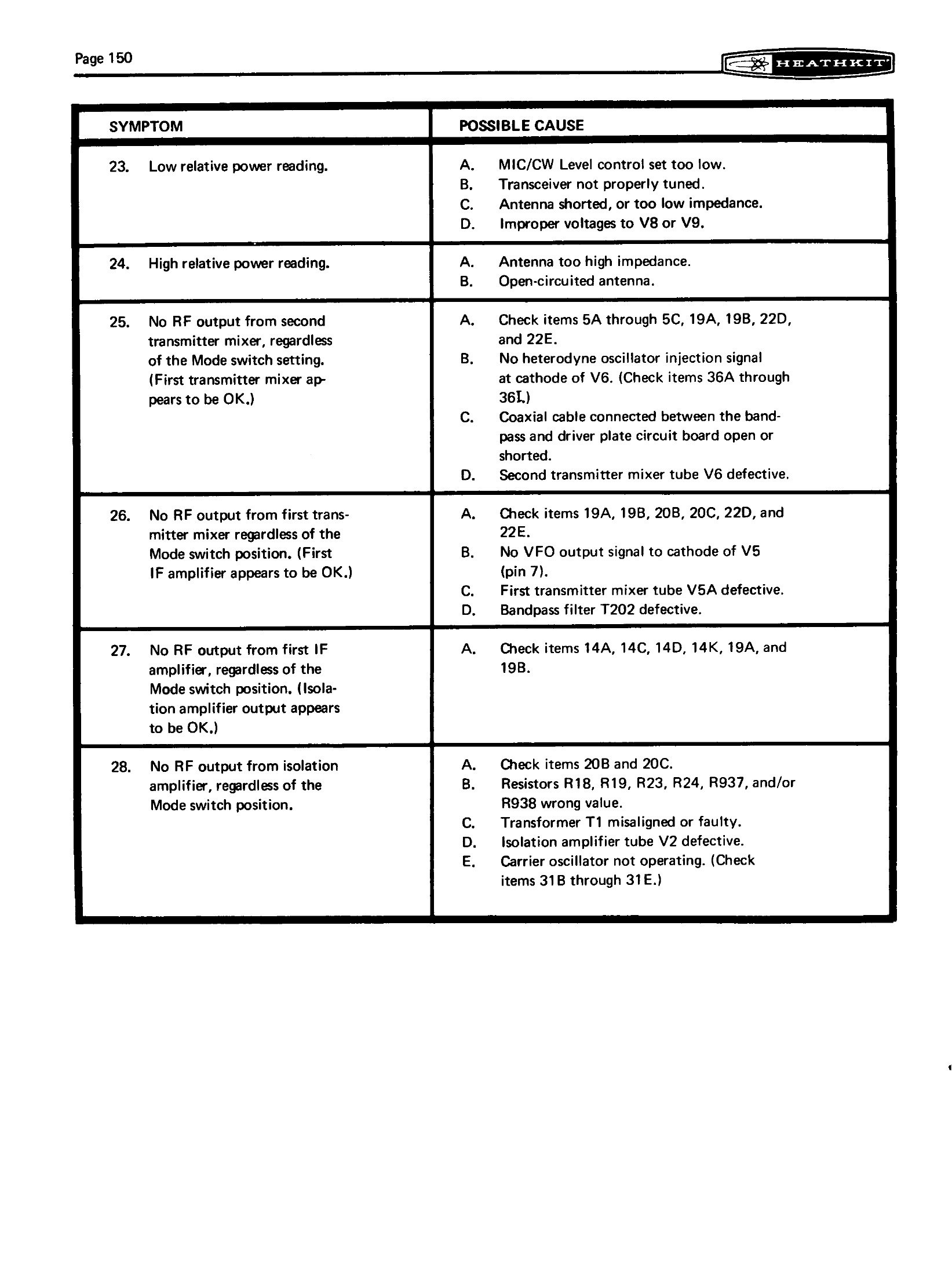
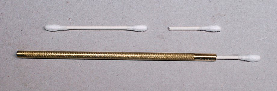
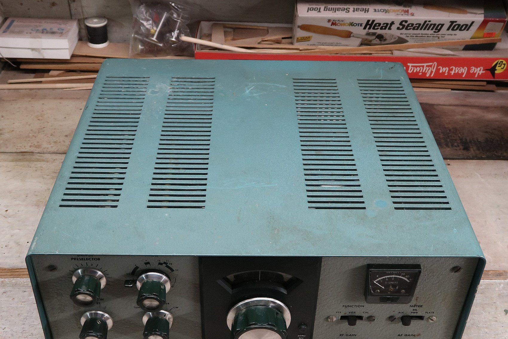
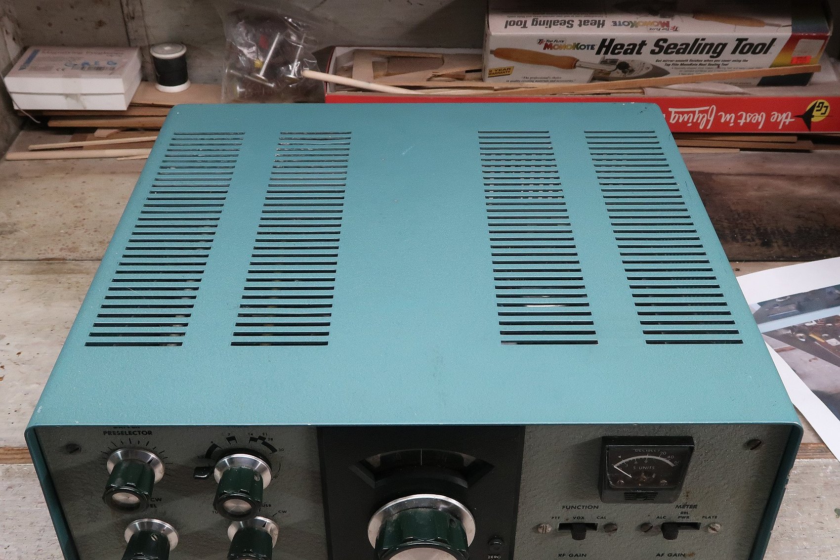
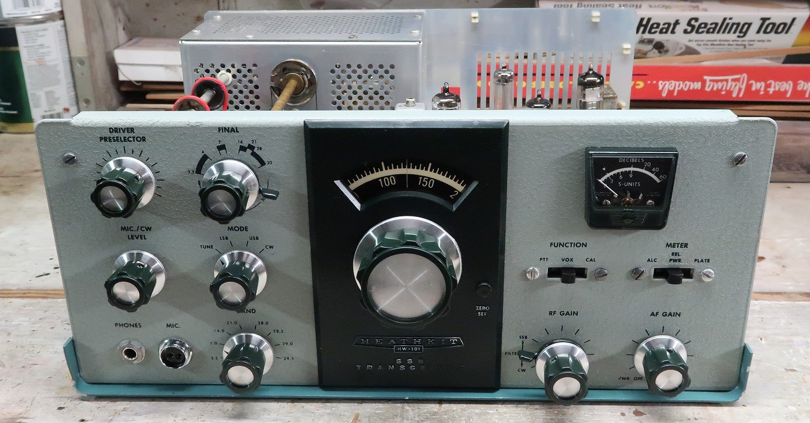
The cabinet, the wrinkle-finish panel and the knobs all clean up, and the methods that work are mildly abrasive rather than solvent-based. One documented approach uses a fine abrasive cream on the cabinet, hot water to flush it and a wax polish afterwards; the panel is divided into sections and worked with a rotary toothbrush and the same cream, applying it before switching the brush on so that it does not spatter, and rinsing each section immediately. The meter face and the dial window are cleaned only with a mild cleaner on a cotton bud, never abrasive. Knobs come off, get scrubbed with a toothbrush, and go back with their brass reducing bushings; bent skirts straighten with pliers.
5.7 Parts, today
The 6146A is still made in quantity as new old stock and is inexpensive; the 6146B is available and should be avoided in this rig. The 6AU6, 6EA8, 12AT7, 12AU7 and OA2 are all common. The 6HS6 is the scarce one, and Practical Wireless advised buying a spare set of valves with any purchase for exactly that reason. The MPF-105 FET is obsolete but equivalents exist. Heterodyne and carrier crystals are interchangeable with SB-102 parts, and salvaged sets are the usual source. The drive belts are a stock item from vintage-electronics suppliers. What is genuinely hard to find is the SBA-301-2 CW filter, which was an extra-cost option that many owners never bought.
Sources
- Heath Company, HW-101 service bulletins, HW-101-1 of 11 February 1971 to HW-101-55 of 19 November 1979. The transcript notes that the 1977 microfiche was never received, so the series is not quite complete. Transcript
- Heathkit Assembly Manual for the HW-101 SSB Transceiver, 595-1277-18 (Heath Company, 1970): “In Case of Difficulty” and the troubleshooting, voltage and resistance charts, pp. 144–156. Internet Archive
- Harris, Bill. “Heathkit HW-101 restoration” and “modifications”. Restoration · Modifications
- Cadman, Phil (G4JCP). “It’s a Classic! The Heathkit HW101.” Practical Wireless, November 2007 — what to look for when buying, and the case for forced-air cooling. Scan
- “Heathkit HW-101 revisited, about mods” — a compilation of owner modifications keyed to Heath’s bulletin numbers. Link
Comments (0)