Vacuum Tube Voltmeters · Volume 2
How It Works
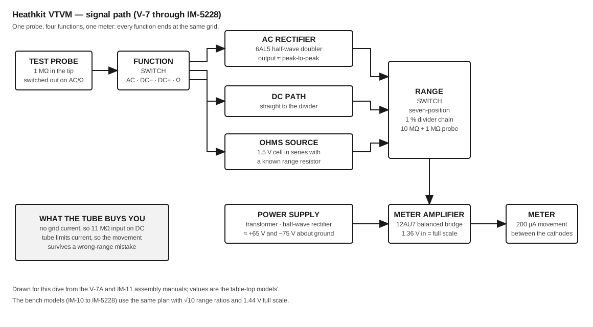
Strip a Heathkit VTVM of its cabinet and there is remarkably little inside: two tubes, a small transformer, a rectifier, one electrolytic capacitor, a handful of ordinary resistors, a dry cell, two wafer switches carrying about twenty precision resistors, and a meter. The whole instrument is a bridge that is thrown out of balance by whatever is applied to one grid, plus three front ends that convert DC volts, AC volts and resistance into a voltage that grid can read. Heath settled on that architecture with the V-7 in 1954 and never seriously changed it again; the IM-5228 that left the catalogue thirty-five years later is the same circuit in a different box.
2.1 The meter amplifier
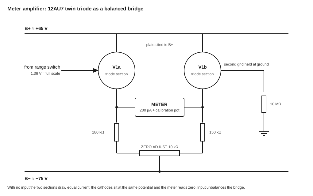
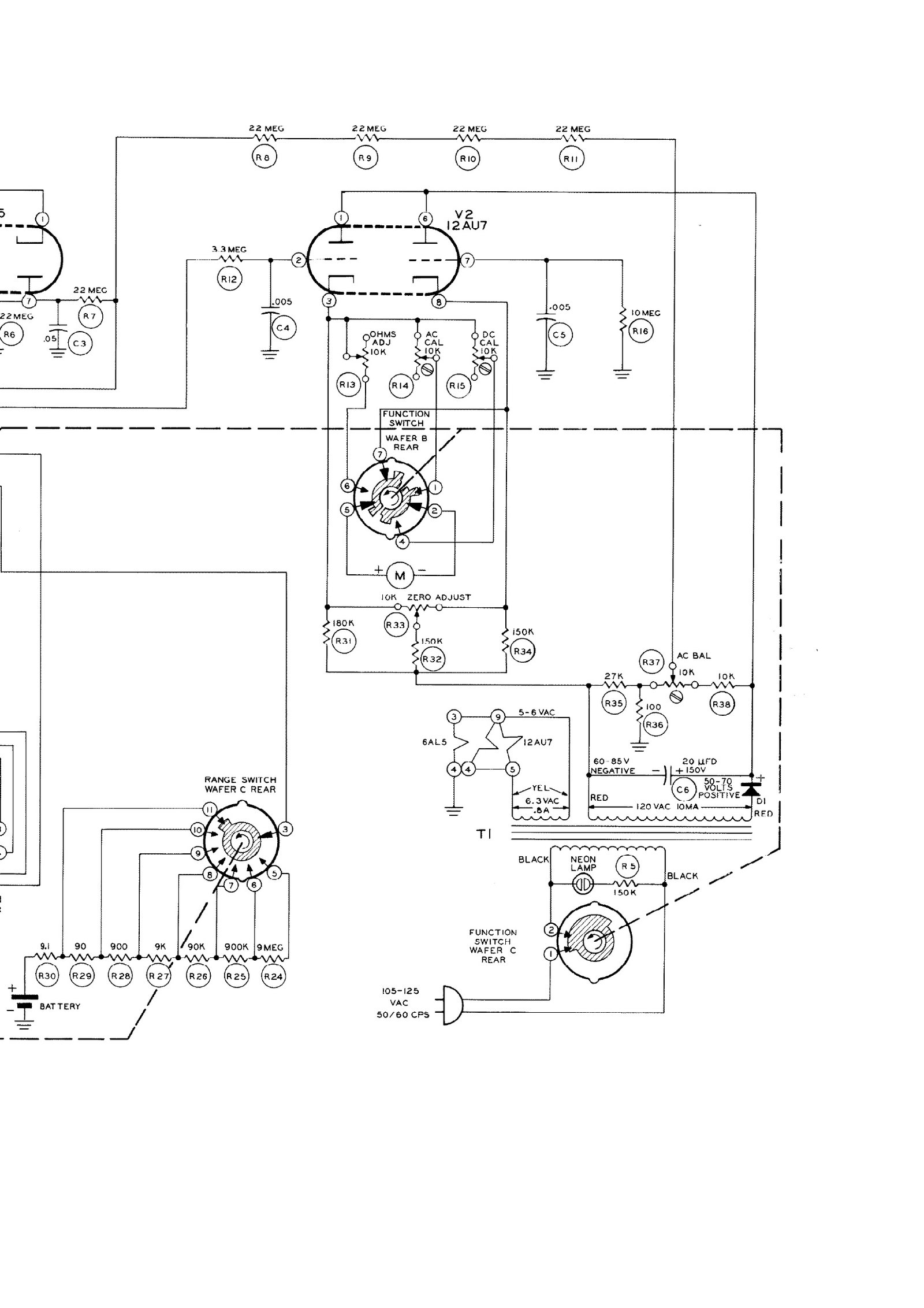
The heart of the instrument is a 12AU7 twin triode wired as a balanced bridge, sometimes called a difference amplifier. Both plates go straight to the positive supply. Each cathode returns through its own resistor to a balance potentiometer whose wiper goes to the negative supply, and the meter sits between the two cathodes. One grid is tied to ground through a large resistance; the other is the input.
With nothing applied, both halves draw the same current, both cathodes sit at the same potential and no current flows through the meter. Apply a voltage to the input grid and that half draws more (or less) current than its partner, the cathodes move apart, and current flows through the movement in proportion. Full-scale deflection corresponds to about 1.36 volts at the grid in the table-top models and about 1.44 volts in the bench models (Eckweiler, Heathkit of the Month #19 and #110).
Three things follow from this arrangement, and they are the whole case for the instrument.
The input draws no current. The grid is biased so that no grid current flows, so the input resistance of the stage is set by the divider in front of it rather than by the meter. That is what buys 11 megohms on DC and, in the ohms function, an input that can be treated as infinite — which is why the same circuit can measure up to 1000 megohms with a single 1.5-volt cell.
The movement is protected. A triode can only pass so much current. Applying 500 volts with the range switch on 1.5 drives the tube into saturation and pins the pointer, but does not burn the coil. Heath advertised this as a “burn-out proof meter circuit” from the V-2 onward.
Zero drifts until the tubes settle. The balance depends on two triode sections tracking each other. A new 12AU7 does not, which is why every Heath VTVM manual ends its calibration section by telling the builder to leave the instrument switched on for 48 hours and then calibrate it again (IM-18 assembly manual, p. 24).
2.2 The DC divider
In the DC function the input passes through the 1-megohm resistor in the probe tip and into a chain of 1 per cent resistors mounted directly on the range switch — not on the circuit board. The chain totals 10 megohms, so with the probe resistor the input resistance is 11 megohms on every range. The range switch taps the chain at the point that makes full-scale input produce full-scale grid voltage.
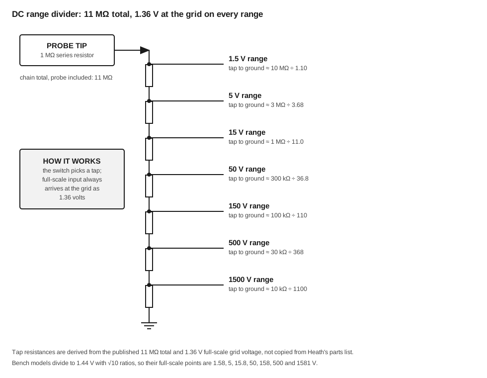
The bench models differ here in a way that matters more than it looks. On the table-top instruments the steps between ranges alternate between 3⅓ and 3, which multiply to a clean decade but are not equal. A decade is 20 dB, so a genuine 10 dB step needs a ratio of √10, or 3.162. Steps of 3 and 3⅓ give 9.54 dB and 10.46 dB instead, so the decibel scale is about half a decibel out when the range is changed. The Deluxe Service Bench models were given divider values with a true √10 ratio throughout, which makes their full-scale points 1.58, 5, 15.8, 50, 158, 500 and 1581 volts. Heath hid the awkward numbers by ending the 0–15 scale short of full scale, at the point corresponding to 15, while the 0–50 scale runs to the end (Eckweiler #110).
2.3 The AC front end, and the problem Heath spent eight years solving
Measuring AC with a DC instrument means rectifying it, and a vacuum diode is an awkward rectifier. It is non-linear at low voltages, and each diode section develops its own contact potential — a small standing voltage that shows up as a residual reading when there is no input at all. Every Heath voltmeter from the V-1 to the V-6 used a different AC circuit, which is the clearest evidence available that none of them worked well enough.
The V-1 and V-2 used a 6H6 dual diode with no balance adjustment at all. The V-4 added an AC BALANCE potentiometer that used the contact potential of one diode section to cancel the other’s — which works only if the right section has the higher potential. Heath’s solution was to pre-age every 6H6 at the factory, measure it, and stamp “REVERSED DIODES” on the carton of those that came out the wrong way round; the manual then carried two sets of wiring steps and two sets of pictorials, and the builder followed whichever matched his tube (Eckweiler #86, reproducing the notice from the V-6 manual). The V-5 tried a loctal 7A6 instead, with a new socket and new wiring; the V-5A quietly went back to the 6H6.
The V-7 ended the argument. Its 6AL5 twin diode is wired as a half-wave voltage doubler: one diode charges a capacitor to the peak of the waveform, the other adds the following half-cycle, and the output is a DC voltage corresponding to the peak-to-peak value of the input. A small bucking current, taken from the power supply through a string of 22-megohm resistors and set by the AC BALANCE control, cancels the contact potential whichever way round the tube happens to be. The circuit worked, the factory tube-selection ritual stopped, and Heath used the same arrangement in every voltmeter it sold afterwards (Eckweiler #19, #110).
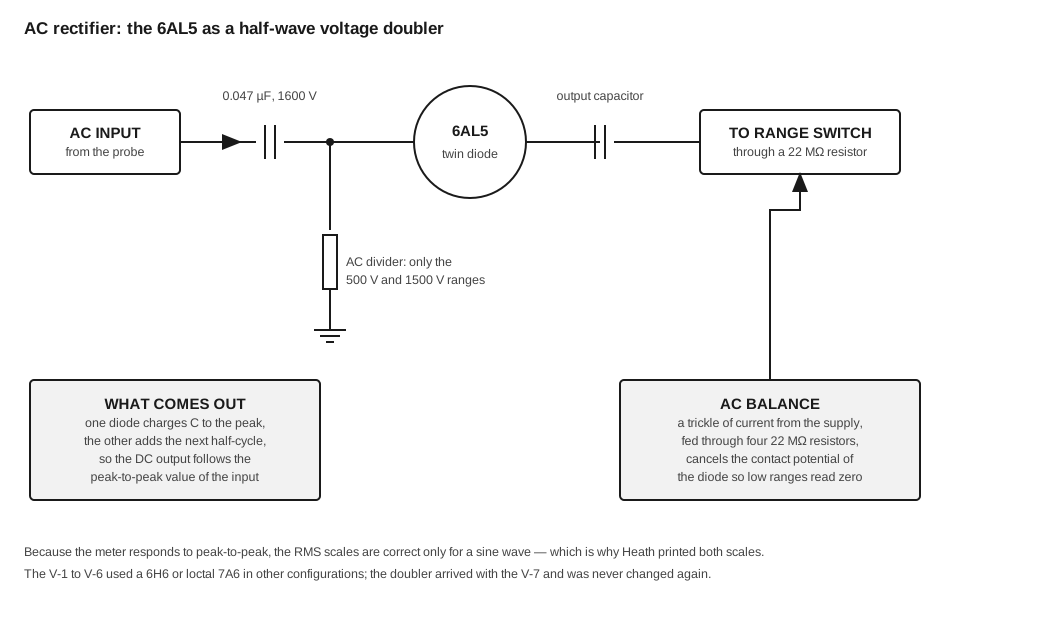
Two consequences are worth stating plainly, because they are the commonest cause of a modern user distrusting a working instrument.
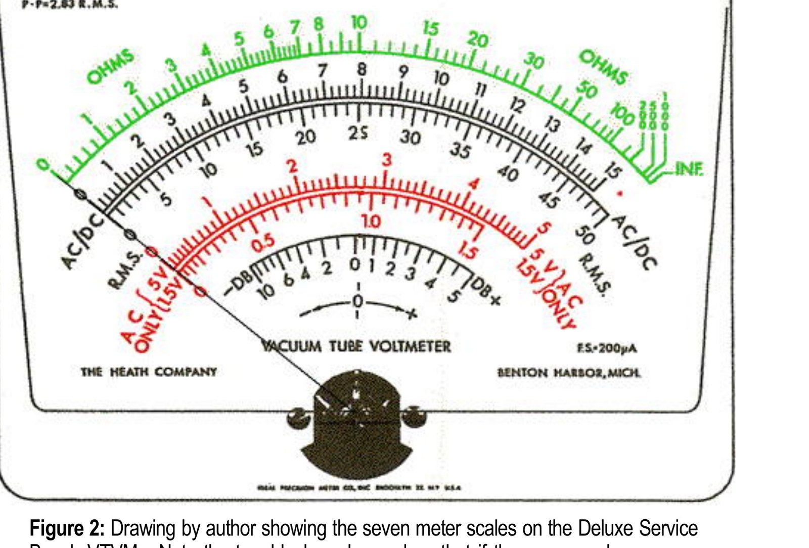
The meter measures peak-to-peak; the RMS scale is arithmetic. The manual’s own specification says the RMS scales read 0.353 of peak-to-peak — that is, they assume a sine wave. On a square wave, a pulse train or a sawtooth, the RMS scale is simply wrong, and the peak-to-peak scale beside it is the one to read. That is exactly why Heath added peak-to-peak scales with the V-7, at the moment television servicing became the instrument’s main market.
AC input impedance is about 1 megohm, not 11. The DC ranges load a circuit hardly at all; the AC ranges load it a hundred times harder, shunted by 35 to 40 picofarads besides. Heath was untroubled by this because it expected real RF work to be done with the 309-series RF probe, which rectifies at the probe tip. The early V-series had higher AC impedance — around 6 megohms — and lost it when the small 6AL5 replaced the 6H6 and had to be protected by a divider (Eckweiler #19). The first IM-10 production run was specified at a worse 320 kΩ; within a few months of the spring 1961 launch Heath changed three resistors and removed a fourth, bringing it to 1 megohm. The Fall–Winter 1961 catalogue still printed the old schematic while quoting the new specification (Eckweiler #110).
2.4 The ohmmeter
The ohms function is the simplest part of the instrument and the one that causes the most trouble sixty years later, because it needs a battery.
A 1.5-volt cell is connected in series with a known resistance — selected by the range switch, from 10 ohms to 10 megohms in decade steps — and the unknown resistance. The junction between the known and unknown resistances goes to the grid. With the leads open, the full battery voltage reaches the grid and the pointer sits at full scale; with them shorted, nothing reaches it and the pointer sits at zero; with an unknown equal to the range resistance, the pointer sits at half scale, which is why the green ohms scale is marked 10 at its centre and the range switch is labelled ×1, ×10 and so on.
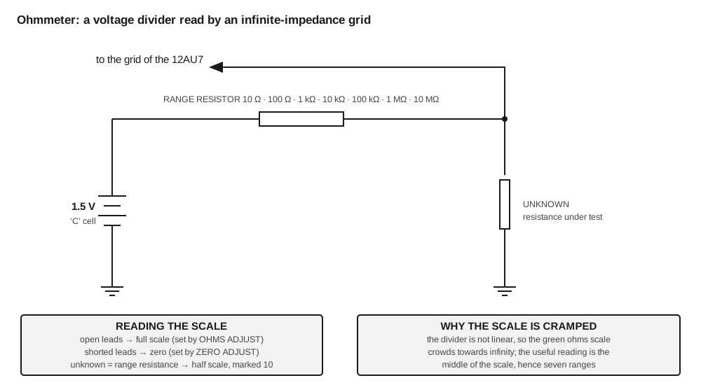
The lowest range is the awkward one. The nominal 10-ohm range resistor is in fact 9.1 ohms; the missing 0.9 ohm is made up by the internal resistance of the battery and the wiring, which is why a tired cell or a corroded battery clip throws off the ×1 range before it affects anything else (Eckweiler #110). That 9.1-ohm resistor is also the instrument’s fuse: measuring a live circuit with the function switch left in OHMS usually destroys it and leaves the rest of the chain intact.
2.5 The power supply
The supply is a half-wave rectifier, a single electrolytic capacitor and a resistive divider, and it is deliberately modest. The transformer secondary supplies about 120 volts at 10 milliamps and 6.3 volts at 0.8 amp for the heaters. The rectified output is referenced to ground part-way down a resistor chain, giving roughly +65 volts and −75 volts about the chassis. The amplifier draws almost nothing, so ripple and regulation hardly matter.
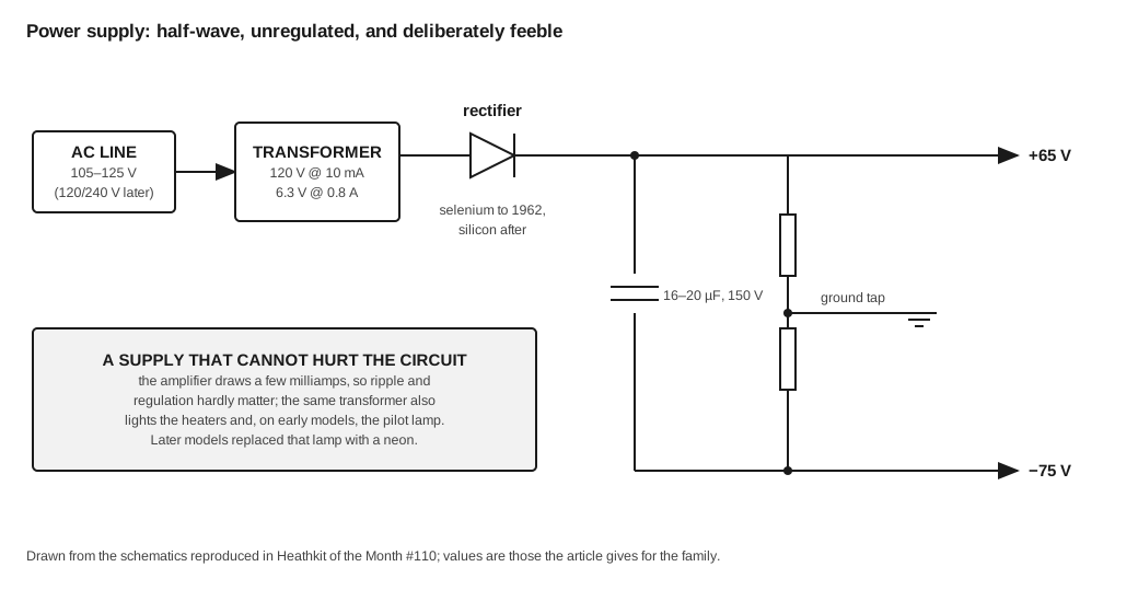
The rectifier is the part that dates an instrument. The V-1 and V-2 used a 6X5 tube. The V-4 and V-4A used a large green selenium stack; the V-5, V-5A and V-6 used a small Sarkes Tarzian selenium rectifier (Heath part V123, renumbered 57-1); the V-7 and V-7A used a sealed Sarkes Tarzian type 57-13 rated 130 V at 50 mA, which cost 48 cents in single quantities in 1963. The bench line changed to a silicon diode (57-27) with the IM-13 in 1963, with no series resistor added and no ill effect (Eckweiler #84, #110).
2.6 The probe
The switching probe introduced with the IM-11 in 1961 replaced three separate leads with one. A slide switch in the probe body selects AC–OHMS, in which the probe tip connects straight through, or DC, in which a 1-megohm resistor is switched into the tip. From the IM-13 the plug was given thicker insulation to stop flashover on the high ranges.
The 1-megohm resistor is in the probe tip for a reason. It isolates the point under test from the capacitance of the cable and the instrument — roughly 160 picofarads of lead, on the IM-13 — which would otherwise detune or load a high-frequency circuit. A well-known modification moves the resistor inside the instrument so that an ordinary probe can be used; Eckweiler recommends against it, on the grounds that it defeats the only purpose the resistor’s position has (#110).
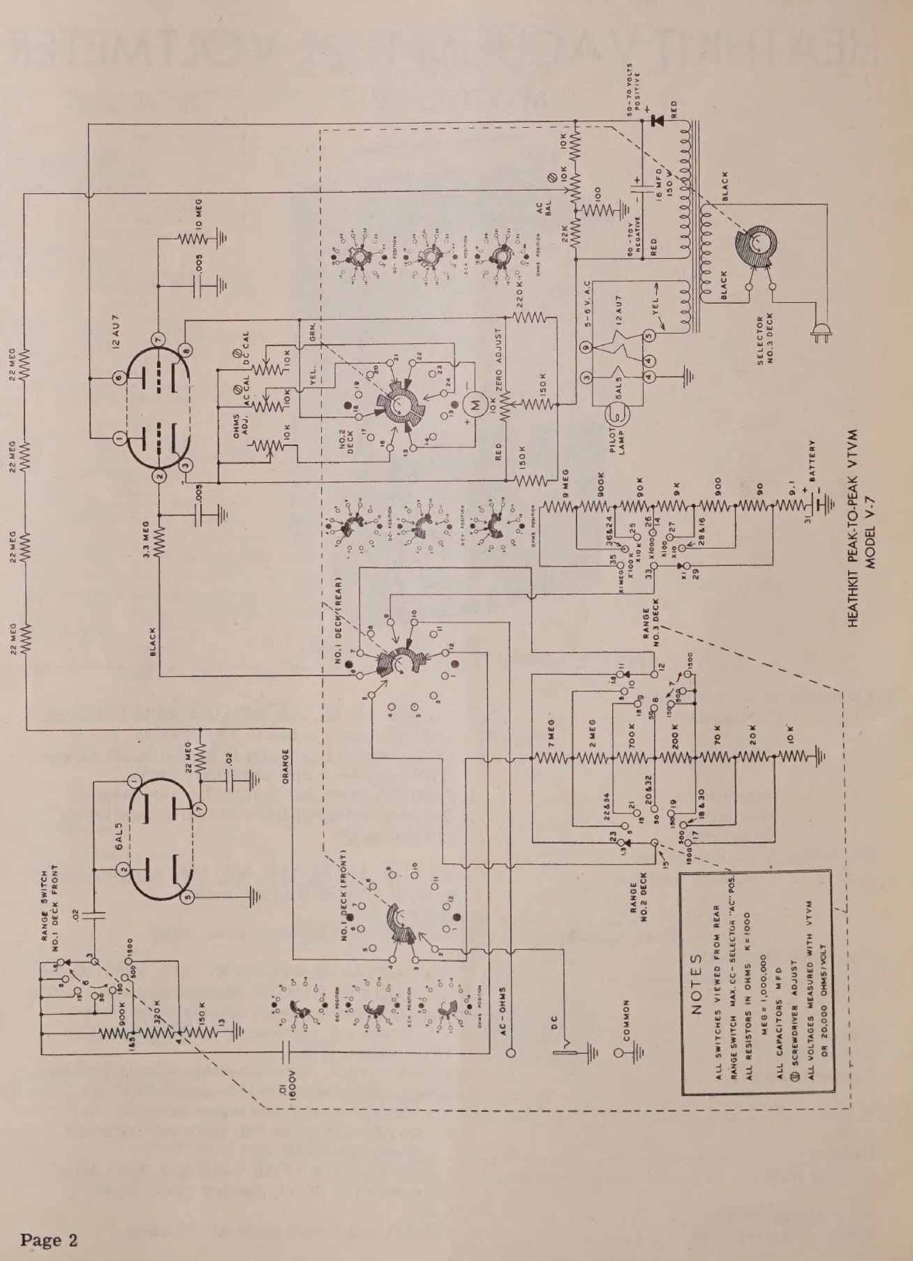
2.7 What changed, model by model
Table 1 — What changed, model by model
| Change | First appears in | Note |
|---|---|---|
| 6X5 rectifier tube | V-1 | Replaced by selenium in the V-4 |
| 200 µA movement | V-2 | The meter maker agreed to supply it once Heath’s volume justified it |
| AC BALANCE control | V-4 | Needed because of diode contact potential |
| ”Reversed diodes” tube selection | V-4A | Carried through the V-6; ended by the V-7 circuit |
| 12AU7 in place of 6SN7 | V-5 | Miniature nine-pin; the tube that stayed to the end |
| Seven ranges, 1.5–1500 V | V-6 | Range structure fixed for the next thirty-seven years |
| Printed circuit board | V-7 | 1/16-inch phenolic; 3/32-inch from the V-7A |
| 6AL5 voltage doubler, peak-to-peak scales | V-7 | The AC circuit that was never changed again |
| Single switching probe | IM-11 | Three leads replaced by one |
| 6-inch meter, √10 ranges, red low-AC scales | IM-10 | The bench line |
| Silicon rectifier, neon pilot, front-panel calibration access | IM-13 | Bench line |
| Dual-primary transformer, three-wire cord | IM-18, IM-28 | 120/240 V operation |
Sources: Eckweiler #19, #84, #86, #110; the assembly manuals cited above; 1970 catalogue for the IM-18’s dual primary and three-wire cord.
2.8 Life after tubes
Heath’s solid-state voltmeters did not replace this circuit so much as sell alongside it. The IM-17 of 1967 used five transistors, a 1.5-volt cell for the ohms circuit and an 8.4-volt mercury cell for everything else, and reached the same 11 megohms on DC without a mains connection (Eckweiler #78). The IM-16 put a solid-state amplifier behind a 6-inch meter with battery or line operation. Both appear in the same catalogues as the IM-18 and IM-28 for a decade.
The most telling product of the transition is the IMA-18-1: two small cans, one containing four field-effect transistors and the other two diodes, that plug into the 12AU7 and 6AL5 sockets of any VTVM from the V-7 onward and turn it into a solid-state instrument with no warm-up. It cost $16.95 in the Spring 1976 catalogue and $19.95 in the Fall 1978 catalogue — a substantial fraction of a new kit — and it is the clearest statement of what the tubes were actually doing in the circuit by then: providing a high-impedance, current-limited difference amplifier, a job a pair of FETs could do without a heater.
Sources
- Eckweiler, Bob (AF6C). “Heathkit of the Month #19: V-7A VTVM.” https://www.w6ze.org/Heathkit/Heathkit_019_V7a.pdf
- Eckweiler, Bob (AF6C). “Heath of the Month #110: Heathkit ‘Deluxe Service Bench’ VTVMs.” https://www.w6ze.org/Heathkit/Heathkit_110_DSB_VTVMs.pdf
- Eckweiler, Bob (AF6C). “Heath of the Month #84 and #86: V-6 VTVM Restoration, parts I and II.” https://www.w6ze.org/Heathkit/Heathkit_084_V6RebuildI.pdf · https://www.w6ze.org/Heathkit/Heathkit_086_V6RebuildII.pdf
- Eckweiler, Bob (AF6C). “Heath of the Month #78: IM-17 Utility Solid-State Voltmeter.” https://www.w6ze.org/Heathkit/Heathkit_078_IM17.pdf
- Heathkit Assembly Manual, Vacuum Tube Voltmeter Model V-7 (595-90). https://archive.org/details/manualsplus_08096
- Heathkit Assembly Manual, Vacuum Tube Voltmeter Model V-7A (595-110). https://archive.org/details/heathkitmanualva00unse
- Heathkit Assembly Manual, Vacuum Tube Voltmeter Model IM-11 (595-486). https://archive.org/details/heathkitassembly00unse_7
- Heathkit Assembly Manual, Vacuum Tube Voltmeter Model IM-18 (595-1154). https://archive.org/details/heathkitassembly00unse_4
- Heathkit Assembly Manual, Service Bench VTVM Model IM-13 (595-629). https://archive.org/details/Heathkit_IM-13_Service_Bench_VTVM
- Heath Company catalogues, 1949–1987, World Radio History. https://www.worldradiohistory.com/Archive-Catalogs/Heathkit_Catalogs.htm
Comments (0)