Vacuum Tube Voltmeters · Volume 5
Restoration and Common Faults
A Heathkit VTVM is one of the easier pieces of vintage test equipment to bring back, because there is so little in it and because almost everything that fails is either cheap or obvious. The commonest cause of a scrapped instrument is not a circuit fault at all but a leaking cell left in the ohmmeter holder for thirty years, and the second commonest is a mains lead whose insulation has turned to dust. Both are fixable. What follows is a survey of the known failure modes, the safe way to bring one up, and the parts and substitutions that work — assembled from the manuals’ own troubleshooting sections and from Bob Eckweiler’s published rebuilds of a V-6 and a V-7A.
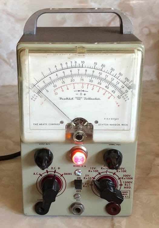
5.1 Safety first, and it is not optional
Three hazards are specific to this instrument.
The chassis is the common lead. The COMMON terminal is bonded to the metalwork. Fitting a modern three-wire cord therefore earths the chassis — which is safer in most respects but means the instrument can no longer be used for floating or differential measurements, and it makes a reversed connection during AC calibration a dead short to earth rather than a mild surprise (Eckweiler, Heathkit of the Month #19).
The AC calibration procedure connects a probe to the live mains. See the calibration volume; the short version is to use an isolation transformer, or a known-good AC meter, rather than following the 1950s instructions literally.
The instrument measures to 1500 volts, and up to 30,000 with the accessory probe. Its own manual’s advice still applies: kill the power before connecting leads if at all possible, keep one hand in a pocket, and remember that a shock from a few hundred volts is usually survivable while the fall that follows it may not be.
For first power-up after decades of storage, the ordinary boat-anchor discipline applies: inspect and replace the mains lead first, bring the instrument up slowly on a variac or through a dim-bulb limiter while watching for smoke or a glowing rectifier, and be ready to switch off. The supply is small — about 10 milliamps at 120 volts — so faults here are undramatic, but a shorted filter capacitor will still cook a sixty-year-old transformer.
5.2 What actually fails
5.2.1 The battery, and what it destroys
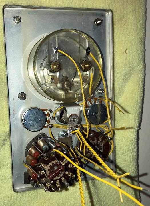
Every Heath VTVM carries a 1.5-volt cell for the ohmmeter, and a great many were left in. Eckweiler’s V-6 arrived with the cell long gone but its damage done: two of the three chassis parts badly corroded, the third less so, and the “almost unobtainium” 7.5 MΩ AC balance potentiometer so far gone that its threaded bushing disintegrated on removal. His verdict on the family as a whole is that a leaking battery “is the most common problem found with VTVMs that use a battery in the ohms circuit” (#110).
The practical rules are simple: take the cell out of any instrument that will sit unused, label the one that is in there with its type and date, and use a brand not prone to leaking. An alkaline cell is fine in the ohms circuit but must not be used for the DC calibration, because its fresh voltage is higher than the 1.55 volts the red dot on the scale assumes.
5.2.2 The selenium rectifier
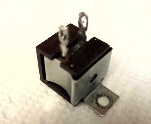
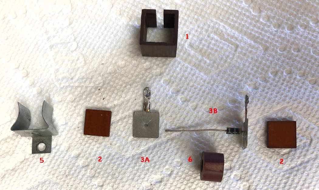
The V-4 through V-7A used selenium rectifiers, which are widely held to deteriorate with age and which fail, when they fail, with a distinctive and memorable smell. Eckweiler reports never having had one of the later sealed 57-13 units fail, but was uneasy enough about the earlier open 57-1 to replace it. The straightforward repair is to remove the rectifier, fit a terminal strip in its place and solder a 1N4004 across it. The authentic repair, which he documents in detail, is to disassemble the original, discard the selenium plates as toxic waste, drill the two terminal end plates, solder a 1N4004 between them inside the original phenolic case, and reassemble — an instrument that looks unmodified and will not need doing again (#84).
No series resistor is needed when substituting silicon. Heath itself made exactly this change in production, from the selenium 57-22 to the silicon 57-27 with the IM-13, and added nothing to compensate; the slightly higher output voltage does no harm (#110).
5.2.3 Capacitors
There are only three or four in the whole instrument, and two of them matter.
The filter electrolytic is 16 µF at 150 volts in the table-top models and 20 µF in the bench models — a working voltage uncomfortably close to the actual voltage across it. Conventional advice is to replace it on sight, and a modern 20 or 22 µF at a higher rating drops straight in. Eckweiler notes, against his own habit of replacing them, that he has yet to find an original that had failed, out of tolerance or even notably leaky, which he attributes to the tiny current the supply delivers.
The 0.01 µF (or 0.047 µF) capacitor in the AC input, rated at 1600 or 2000 volts, is the one to take seriously. It sits between the probe and the rectifier tube on every AC range, so if it becomes leaky the instrument reads high — and it is leaking DC from whatever high-voltage point is being measured. Replace it, and replace it with the original voltage rating; the value is common, the rating is not, and it may need ordering (#19 and #86).
5.2.4 The 9.1-ohm resistor, which is really a fuse
At the bottom of the ohms divider chain sits a 9.1-ohm resistor that makes up the nominal 10-ohm range in combination with the battery and lead resistance. It is also the part that dies when someone measures a live circuit with the function switch left on OHMS, and it usually dies alone — which is the point. A VTVM that reads nothing on ×1 and is otherwise healthy has almost certainly lost it. Replace it with the same value, then check the rest of the ohms chain for collateral damage (#19).
5.2.5 Switches
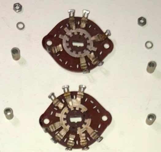
The range and function switches have silver-plated contacts and phenolic wafers, and their condition sets how stable the readings are. Clean them with a proper contact cleaner and nothing abrasive: abrasives take off the silver plating and guarantee more trouble later. Keep cleaner off the phenolic insulation, which matters more here than in most equipment because the ohmmeter is working up to 1000 megohms. Check the wafers for cracks, and check that the long through-bolts holding the wafers are tight, since loose switch hardware causes misalignment and intermittent contact (#19, #86).
5.2.6 The meter
Check the movement before buying: the pointer should return to the same place every time, and the mechanical zero should reach the scale zero. A meter that behaves erratically with the power off is often not faulty at all — static on the plastic face drags the pointer, and wiping the face with a little dishwashing detergent clears it. Cracks in the face or a bent pointer are a different matter, as replacement meters are the hardest part of the instrument to find.
5.2.7 The tubes, and the zero that will not sit still
A 12AU7 and a 6AL5 are among the most plentiful tubes ever made, so replacement is easy; the subtlety is that this circuit depends on the two triode sections of the 12AU7 matching each other and staying matched as they warm. A zero that shifts noticeably between DC+ and DC− means an unaged or tired tube rather than a calibration error. Leave the instrument on for 48 hours and recalibrate before condemning anything. The 6AL5 and its surrounding components are also what suffer if high AC voltages are measured on a low range, so a VTVM with damaged AC ranges is worth checking there first.
5.2.8 The probe
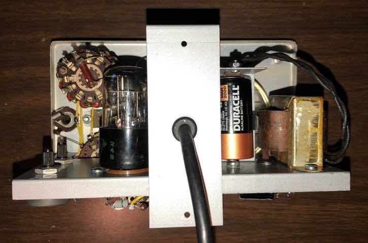
The switching probe is a common casualty, and a missing one is a real problem because the 1-megohm resistor in its tip is part of the instrument’s specification: without it the DC input resistance is 10 megohms, not 11, and every DC reading is 10 per cent adrift. Heath sold the PKW-4 as a wired replacement for the IM-18, IM-28, IM-5218 and IM-5228 into the late 1980s, and it turns up second-hand.
A modification circulates that moves the 1-megohm resistor inside the instrument and switches it in with the function switch, so that any ordinary probe can be used. It works electrically. Eckweiler recommends against it on the grounds that the resistor’s position — at the tip, ahead of the cable — is the whole reason it exists: it isolates the point under test from the cable’s capacitance, which is roughly 160 picofarads on a bench model. Move it and high-frequency measurements start to lie (#110).
5.3 Working through a fault
The manuals are the best diagnostic document available, because Heath printed the troubleshooting chart in the assembly manual rather than in a separate service book. The chart is organised by symptom — completely inoperative, inability to obtain DC balance, AC inoperative, inaccurate readings, ohms inaccurate — and each symptom lists the three or four components that can cause it, by reference designator.
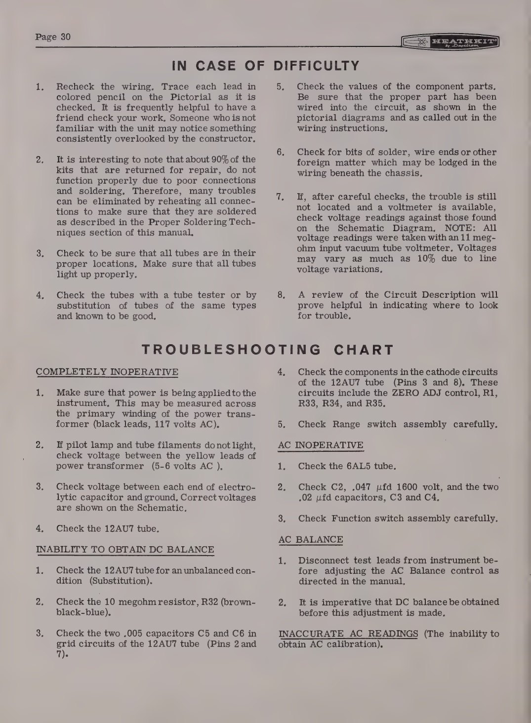
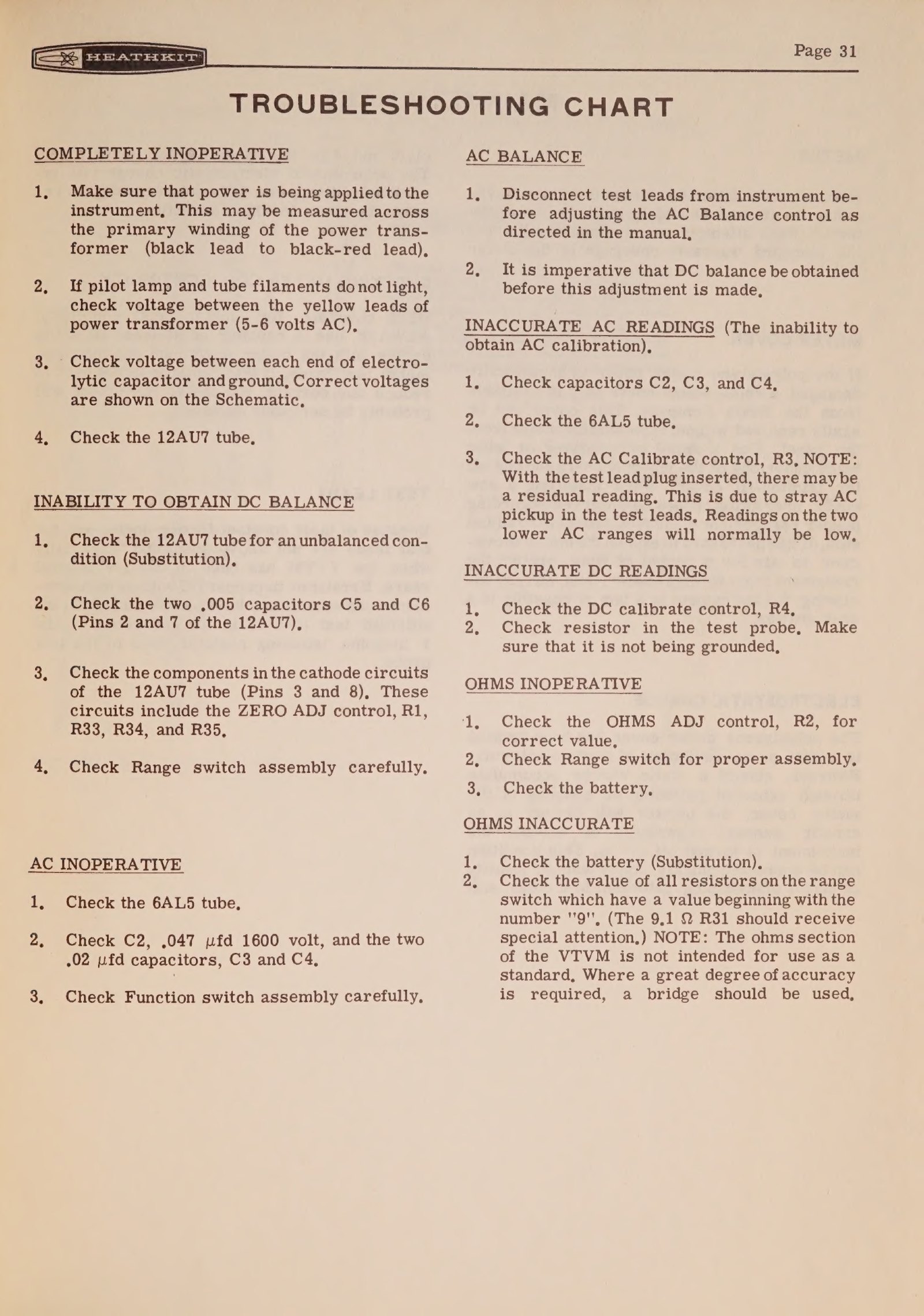
A sensible order of work on an unknown instrument: inspect for battery damage and replace the mains lead; check the ohms chain and particularly the 9.1-ohm resistor; replace the filter electrolytic and the high-voltage AC capacitor; clean the switches and controls; check the tubes; bring it up on a variac; then do a preliminary calibration, leave it running for 24 to 48 hours, and calibrate again.
5.4 Parts, substitutions and what is hard to find
Table 1 — Parts, substitutions and what is hard to find
| Part | Availability | Notes |
|---|---|---|
| 12AU7, 6AL5 | Common | Any reputable brand; matched sections are not required but a well-aged tube behaves better |
| Filter electrolytic 16–20 µF 150 V | Easy | 22 µF at 160 V or more; axial types are getting expensive |
| 0.01 µF at 1600–2000 V | Harder | Order the voltage rating, not just the value |
| Precision divider resistors | Hard | Modern 1 per cent metal-film types are electrically better than the originals; awkward values like 700 kΩ and 320 kΩ may need series combinations |
| 7.5 MΩ AC balance pot (V-4A to V-6) | Very hard | New old stock only |
| 10 kΩ panel controls | Easy, with a caveat | Modern imports have 8 mm bushings rather than 3/8 inch; a turn of 22-gauge wire round the bushing takes up the slack |
| Selenium rectifier | Obsolete | 1N4004, either on a terminal strip or hidden inside the original case |
| #47 pilot lamp / NE-2 neon | Easy | An LED replacement for the #47 reduces the load on the filament winding |
| Meter movement | Hard | Treat the meter as the instrument’s irreplaceable part |
| Switching probe | Moderate | PKW-4 second-hand, or rebuild the original around a new 1 MΩ resistor |
| Hardware | Easy | Heath used slotted binder-head screws, mostly 6-32 × 3/8”, 6-32 × 1/4” and 4-40 × 1/4”; Phillips heads look wrong |
Sources: Eckweiler #84, #86, #110.
5.5 Modifications, period and modern
The factory one. Heath’s own IMA-18-1, two plug-in cans containing four FETs and two diodes, replaces the 12AU7 and 6AL5 in any VTVM from the V-7 onward and makes the instrument instant-on and drift-free. It is the only modification the manufacturer endorsed, and it is reversible.
Battery elimination. Several published modifications rectify part of the filament winding and regulate it to 1.5 volts, doing away with the cell that causes most of the damage. Eckweiler’s caution is worth repeating: the filament winding is already loaded, especially on models with an incandescent pilot lamp, and any such supply must present about 0.9 ohm of internal resistance to make up the ohms chain correctly. The bench models have room inside for a small separate transformer and regulator, which is the tidier answer.
A three-wire mains lead. Reasonable on safety grounds, with the caveat above about the chassis then being earthed. Where the original two-wire cord is kept, it is worth fitting a fuse in the primary and replacing any capacitor across the line with a modern safety type.
What not to do. Drilling the panel or chassis, moving the probe resistor, and substituting an ordinary carbon-composition resistor for one of the 1 per cent precision types in the divider chain all reduce the instrument without improving it.
5.6 Cosmetics
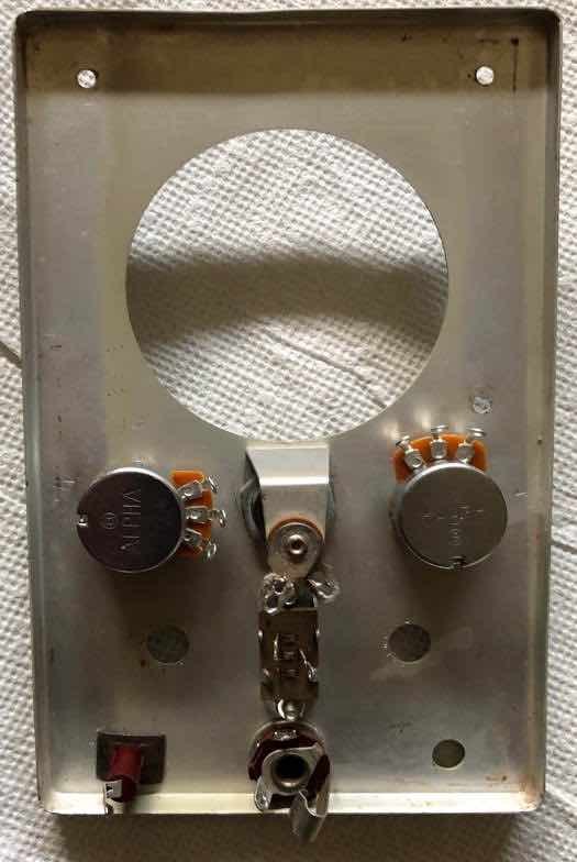
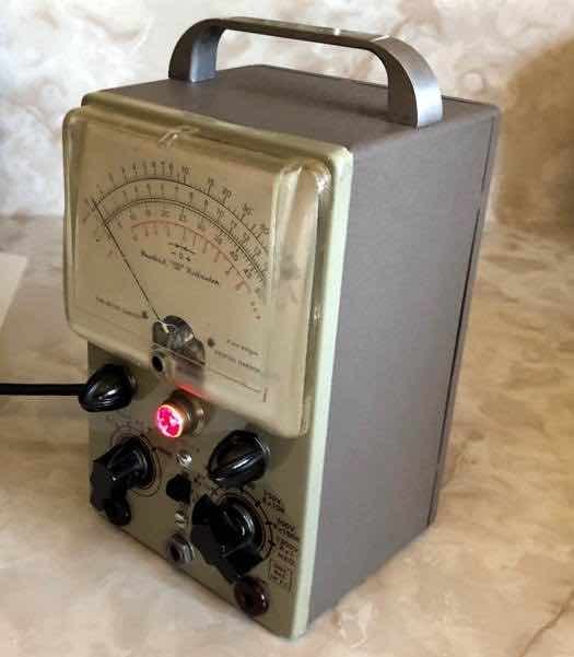
Panels normally clean up with warm water and detergent; scratches are usually left alone, since repainting a screened panel destroys the lettering. Cabinets are harder. The early cabinets are a grey wrinkle finish that is effectively impossible to match — Eckweiler’s solution on the V-6 was to leave the original wrinkle paint as a base texture and cover it with a satin top coat close to the original colour. The later charcoal-grey and beige-and-brown finishes are easier to approximate.
5.7 Is it worth restoring?
For a modern bench the honest answer is that a VTVM is not a general-purpose meter — a twenty-dollar digital multimeter beats it on DC accuracy, resolution and safety. What it still does better is specific: it is immune to RF fields in a way a digital meter is not, so it can be used around a working transmitter; its input loads a high-impedance circuit less than most meters on DC; its analogue pointer shows a trend, a null or a drift at a glance; and it will sit switched on all day for a few watts. For anyone aligning tube equipment, those four properties are exactly the ones that matter, which is why Heath was still selling the design in 1989 and why the instruments are still on benches now.
Sources
- Eckweiler, Bob (AF6C). “Heathkit of the Month #19: V-7A VTVM” (restoration notes). https://www.w6ze.org/Heathkit/Heathkit_019_V7a.pdf
- Eckweiler, Bob (AF6C). “Heath of the Month #84: V-6 VTVM Restoration Part 1 — Siliconizing the Selenium Rectifier.” https://www.w6ze.org/Heathkit/Heathkit_084_V6RebuildI.pdf
- Eckweiler, Bob (AF6C). “Heath of the Month #86: V-6 VTVM Restoration Part II.” https://www.w6ze.org/Heathkit/Heathkit_086_V6RebuildII.pdf
- Eckweiler, Bob (AF6C). “Heath of the Month #110: Heathkit ‘Deluxe Service Bench’ VTVMs.” https://www.w6ze.org/Heathkit/Heathkit_110_DSB_VTVMs.pdf
- Heathkit Assembly Manual, Model IM-11 (595-486). https://archive.org/details/heathkitassembly00unse_7
- Heathkit Vacuum Tube Voltmeter Model IM-5218 manual (595-1972), 1977. https://archive.org/details/IM-5218-manual
- Heath Company catalogues, World Radio History. https://www.worldradiohistory.com/Archive-Catalogs/Heathkit_Catalogs.htm
Comments (0)