Vacuum Tube Voltmeters · Volume 6
Reference
Everything in this volume is drawn from primary documents: Heath’s own assembly manuals, scanned and hosted at the Internet Archive, and Heath’s catalogues and flyers, scanned at World Radio History. Where a figure appears in two sources with different values, both are given. The manual list at the end records the data needed for the hosting decision set out in the project’s rules — publication year, whether a copyright notice was seen, and whether a copyright-renewal search has been made.
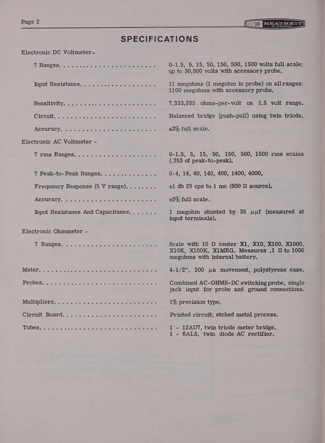
6.1 Full specifications: the table-top models
Table 1 — Full specifications: the table-top models
| V-7 / V-7A | IM-11 | IM-18 | IM-5218 | |
|---|---|---|---|---|
| Years | 1954–1961 | 1961–1969 | 1969–1977 | 1977–1983 |
| DC ranges, full scale | 1.5, 5, 15, 50, 150, 500, 1500 V | same | same | same |
| DC input resistance | 11 MΩ (1 MΩ in probe) | same | same | same |
| DC sensitivity | 7,333,333 Ω/V on 1.5 V | same | same | same |
| DC accuracy | ±3% of full scale | same | same | same |
| AC ranges, RMS | 1.5, 5, 15, 50, 150, 500, 1500 V | same | same | same |
| AC ranges, peak-to-peak | 4, 14, 40, 140, 400, 1400, 4000 V | same | same | same |
| AC accuracy | ±5% of full scale | same | same | same |
| Frequency response | ±1 dB, 42 c/s – 7.2 Mc (5 V range, 600 Ω) | ±1 dB, 25 c/s – 1 Mc | ±1 dB, 25 Hz – 1 MHz | same |
| AC input impedance | ≈1 MΩ shunted by 35 pF | 1 MΩ, 35 pF | 1 MΩ, 35 pF | 1 MΩ, 35 pF |
| Ohms ranges | ×1, ×10, ×100, ×1000, ×10K, ×100K, ×1 MEG (10 Ω centre) | same | same | same |
| Ohms span | 0.1 Ω – 1000 MΩ | same | same | same |
| Meter | 4½ in, 200 µA, polystyrene case | same | same | same |
| Multipliers | 1% precision | same | same | same |
| Circuit board | 1/16 in XXP (V-7); 3/32 in (V-7A) | printed circuit | printed circuit | printed circuit |
| Tubes | 12AU7, 6AL5 | same | same | same |
| Battery | 1.5 V cell (supplied on early kits) | 1.5 V “C” cell | 1.5 V “C” cell, not supplied | same |
| Power | 105–125 V, 50–60 c/s, 10 W | same | 120/240 V, 50/60 Hz | 120/240 V |
| Probe | three separate leads | combination AC-OHMS-DC switching probe | same | same |
| Cabinet | 7⅜ × 4 11/16 × 4⅛ in | same | 7⅜ × 4⅝ × 4¼ in | same |
| Shipping weight | 7 lb | 5 lb | 5–6 lb | 5 lb |
Sources: V-7 manual, V-7A manual, IM-11 manual, and the 1972, 1976 and 1978 catalogues.
6.2 Full specifications: the Deluxe Service Bench models
Table 2 — Full specifications: the Deluxe Service Bench models
| IM-10 / IM-32 | IM-13 | IM-28 | IM-5228 | |
|---|---|---|---|---|
| Years | 1961–62 / 1962–63 | 1963–1969 | 1969–1977 | 1977–1989 |
| Layout | vertical | horizontal, gimbal bracket | horizontal, gimbal bracket | horizontal, gimbal bracket |
| Meter | 6 in, 200 µA, seven scales | same | same | same, new style face |
| DC ranges | 1.5, 5, 15, 50, 150, 500, 1500 V (true √10 steps) | same | same | same |
| DC input resistance | 11 MΩ (1 MΩ in probe) | same | same | same |
| AC input impedance | 320 kΩ / 30 pF (early IM-10); 1 MΩ / 30 pF thereafter | 1 MΩ / 40 pF (plus ≈160 pF of lead) | 1 MΩ / 40 pF | 1 MΩ / 40 pF |
| Extra AC scales | separate 1.5 V and 5 V red scales | same | same | same |
| Decibels | −10 to +65 dB, 10 dB steps between ranges | same | same | same |
| Accuracy | DC ±3%, AC ±5% of full scale | same | same | same |
| Frequency response | ±1 dB, 25 c/s – 1 Mc | same | same | same |
| Rectifier | selenium 57-22 | silicon 57-27 | silicon | silicon |
| Pilot lamp | #47 in jewelled holder | neon assembly | NE-2E in lens | NE-2E in lens |
| Fuse | ¼ A (IM-10); ⅛ A slow-blow (IM-32) | none | none | none |
| Mains | 120 V primary | 120 V primary | 105–125 / 210–250 V | 105–125 / 210–250 V |
| Calibration access | cabinet off | three front-panel holes | same | same |
| Size | 9½ × 6½ × 5 in | 5 × 12 11/16 × 4¾ in | same | same |
Sources: Eckweiler, Heathkit of the Month #110; IM-13 manual; the 1961, 1967, 1972 and 1980 catalogues.
6.3 The early models at a glance
Table 3 — The early models at a glance
| Model | Tubes | Rectifier | Meter | Ranges | Notes |
|---|---|---|---|---|---|
| V-1 | 6SN7, 6H6, 6X5 | 6X5 tube | small, 500 µA | 5 voltage ranges to 1000 V | two cells for the ohmmeter; 8 lb shipping |
| V-2, V-2A | 6SN7, 6H6, 6X5 | 6X5 tube | 200 µA | 6 ranges | sixth range added, 10 V and R×10M |
| V-4 | 6SN7, 6H6 | selenium (V97) | larger | 6 ranges | AC balance control added |
| V-4A | 6SN7, 6H6 | selenium | 4½ in, 200 µA | 6 ranges | revised AC circuit; ½% dividers advertised |
| V-5 | 12AU7, 7A6 | selenium (V123/57-1) | 4½ in | 6 ranges | formed cabinet; single 1.5 V cell |
| V-5A | 12AU7, 6H6 | selenium | 4½ in | 6 ranges | 7A6 abandoned |
| V-6 | 12AU7, 6H6 | selenium | 4½ in | 7 ranges, 1.5–1500 V | R×100K added; “reversed diodes” tube selection |
Sources: Eckweiler #19 and #84; V-2, V-4, V-5A and V-6 manuals.
6.4 Prices, catalogue by catalogue
Table 4 — Prices, catalogue by catalogue
| Catalogue | Table-top | Bench | Wired version |
|---|---|---|---|
| December 1949 flyer | V-4, $24.50 | — | — |
| January 1951 flyer | V-4A, $23.50 | — | — |
| September 1951 flyer | V-5, $24.50 | — | — |
| Winter 1955 flyer | V-7, $24.50 | — | — |
| 1956 catalogue | V-7A, $24.50 | — | — |
| 1959 catalogue | V-7A, $25.95 | — | — |
| Fall–Winter 1961 | IM-11, $29.95 | IM-10, $32.95 | IMW-11, $46.75 |
| Fall–Winter 1962–63 | IM-11, $24.95 | IM-32, $32.95 | IMW-11, $46.75 |
| 1967 catalogue | IM-11, $24.95 | IM-13, $32.95 | IMW-11 $39.95; IMW-13 $49.95 |
| 1970 catalogue | IM-18 | IM-28, $39.95 | IMW-18, $48.95 |
| 1972 catalogue | IM-18, $29.95 | IM-28, $39.95 | IMW-28, $59.95 |
| Spring 1976 | IM-18, $36.95 | IM-28, $46.95 | SM-20A $70; SM-21A $90 |
| Fall 1978 | IM-5218, $44.95 | IM-5228, $54.95 | SU-5218 $110; SU-5228 $120 |
| 1980 catalogue | IM-5218, $49.95 | IM-5228, $59.95 | SM-5218 $95; SM-5228 $120 |
| 1983 catalogue | — | IM-5228, $79.95 | — |
| Fall 1985 | — | IM-5228, $79.95 | — |
| Fall 1987 | — | IM-5228, $89.95 | — |
| Christmas 1989 | — | IM-5228, $129.95 (per Eckweiler) | — |
All figures are kit prices from the catalogue scans at World Radio History except the last, which comes from Eckweiler #110. The Winter 1991 catalogue, which has a searchable text layer, lists no vacuum-tube voltmeter at all.
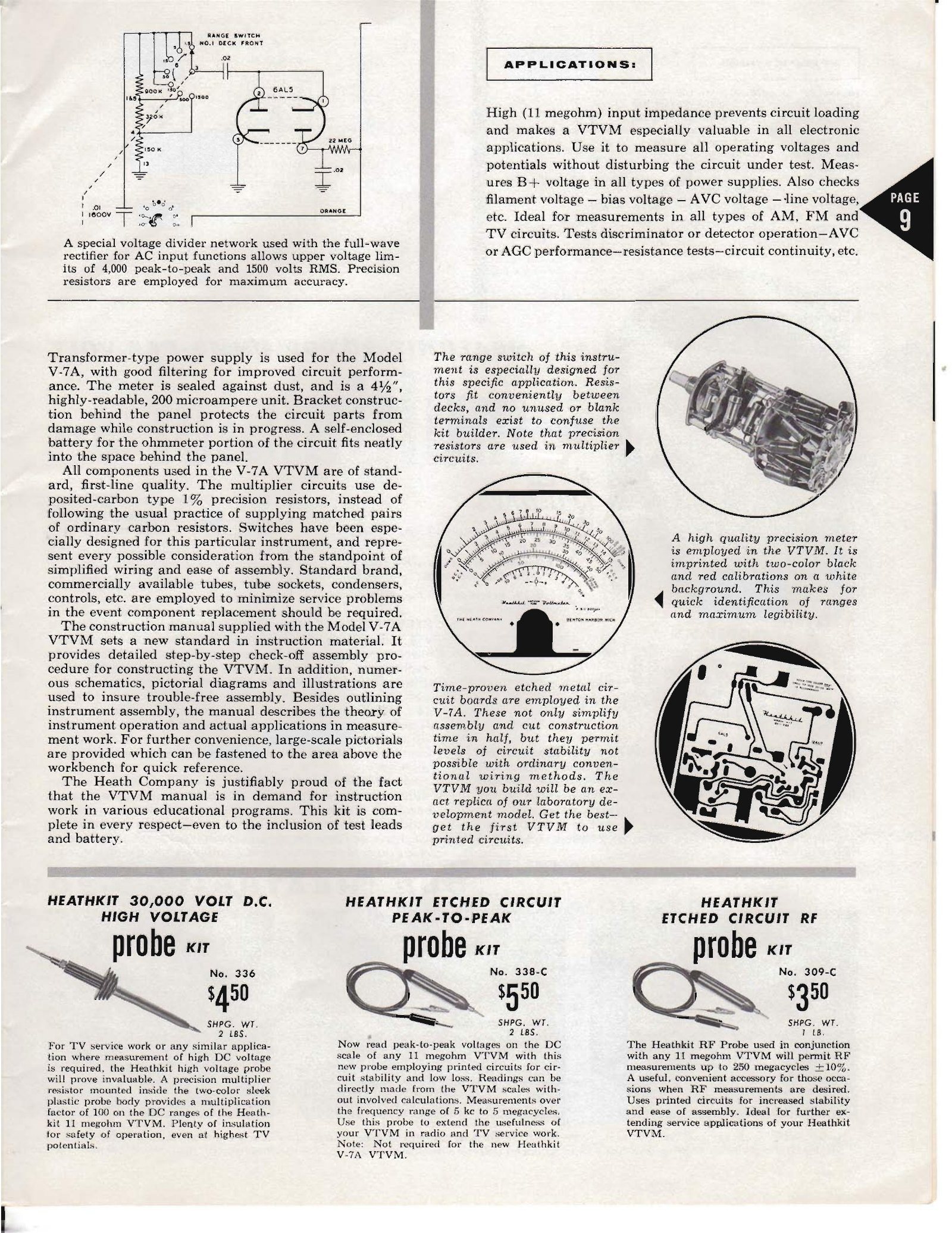
6.5 Accessories
Table 5 — Accessories
| Part | What it is | Notes |
|---|---|---|
| 309 / 309-A / 309-B / 309-C | RF probe, crystal-diode detector at the tip | 1949–c.1970; 309-C rated 30 V RF, 500 V DC maximum |
| 309W-C | Factory-wired 309-C | late production |
| 310 | 10 kV DC high-voltage probe, ×10 | 1949 to mid-1950 |
| 336 / 336-W | 30 kV DC high-voltage probe, ×100; 1090 MΩ 2% resistor | from mid-1950; wired version from about 1961 |
| 338 / 338-B / 338-C | Peak-to-peak probe, 5 kHz–5 MHz | 1952 to about 1960 |
| PK-3 / PK-3A, PKW-3 / PKW-3A | RF probe for the later meters | from early 1970; PK-3A from about mid-1979, kit version sold to late 1987 |
| PKW-4 | Wired replacement switching probe for IM-18, IM-28, IM-5218, IM-5228 | 1981 to late 1986 |
| IMA-18-1 | Solid-state plug-in replacements for the 12AU7 and 6AL5 | instant-on conversion; 4 FETs and 2 diodes |
| IMA-100-10 | ×100 DC multiplier probe for 10 MΩ instruments | $14.95 in 1983 |
| EF-1 | ”How To Understand and Use Your Vacuum Tube Voltmeter” course | $9.95; bundled as EF-1-3 (with IM-11) and EF-1-6 (with IM-28) |
Sources: Eckweiler #118 and #119; catalogues of 1949, 1961, 1972, 1978, 1980 and 1983.
6.6 Related Heath instruments
The AC VTVM line — AV-1 (1951), AV-2 (1952), AV-3 (1956), IM-21 (1961), IM-38 (1969) and IM-5238 (1977) — amplifies before rectifying and is a different instrument for audio work; Eckweiler covers it in Heathkit of the Month #47 and #68. The solid-state voltmeters that overlapped with the VTVMs are the IM-17 utility voltmeter (1967–1977), the IM-16 solid-state volt-ohm meter and the IM-25 high-impedance VOM. The EUW-24 Science Series VTVM was a version built for Heath’s educational line.
6.7 Manuals and documents
Heath’s manual part numbers run 595-nnn, and later 595-nnnn-nn with a revision suffix. The list below gives every edition located online, with the data the project’s hosting rule requires. No copyright-renewal search has been carried out in the Catalog of Copyright Entries for any of these titles; “notice seen” records only what is visible on the scan examined here, and the absence of a notice in a poor scan is not proof that the printed manual carried none.
Table 6 — Manuals and documents
| Title | Part no. | Date evidence | Copyright notice seen | Free scan |
|---|---|---|---|---|
| Assembling and Using Your Heathkit Vacuum Tube Voltmeter, Model V-2 | not visible on scan | undated; V-2 sold 1949 | none seen | archive.org |
| …Model V-4 | not visible | V-4 sold from Jan 1950 | none seen | archive.org · second copy |
| …Model V-4A | not visible | V-4A sold 1950–51 | none seen | archive.org; schematic only |
| …Model V-5A | 595-2 | V-5A sold 1952 | none seen | archive.org · second copy |
| …Model V-5 (schematic) | — | — | none seen | archive.org |
| …Model V-6 | 595-40 | print date 11/13/53 on the scan | none seen | archive.org · second · third |
| …Model V-7 | 595-90 | ”Copyright 1954, Heath Company” on the cover; print date 2/10/55 inside | yes, 1954 | archive.org |
| …Model V-7A | 595-110 | one printing carries “Copyright 1960” with print date 6/30/61 | yes, 1960 (on the 1961 printing) | archive.org, DLARC · second · third |
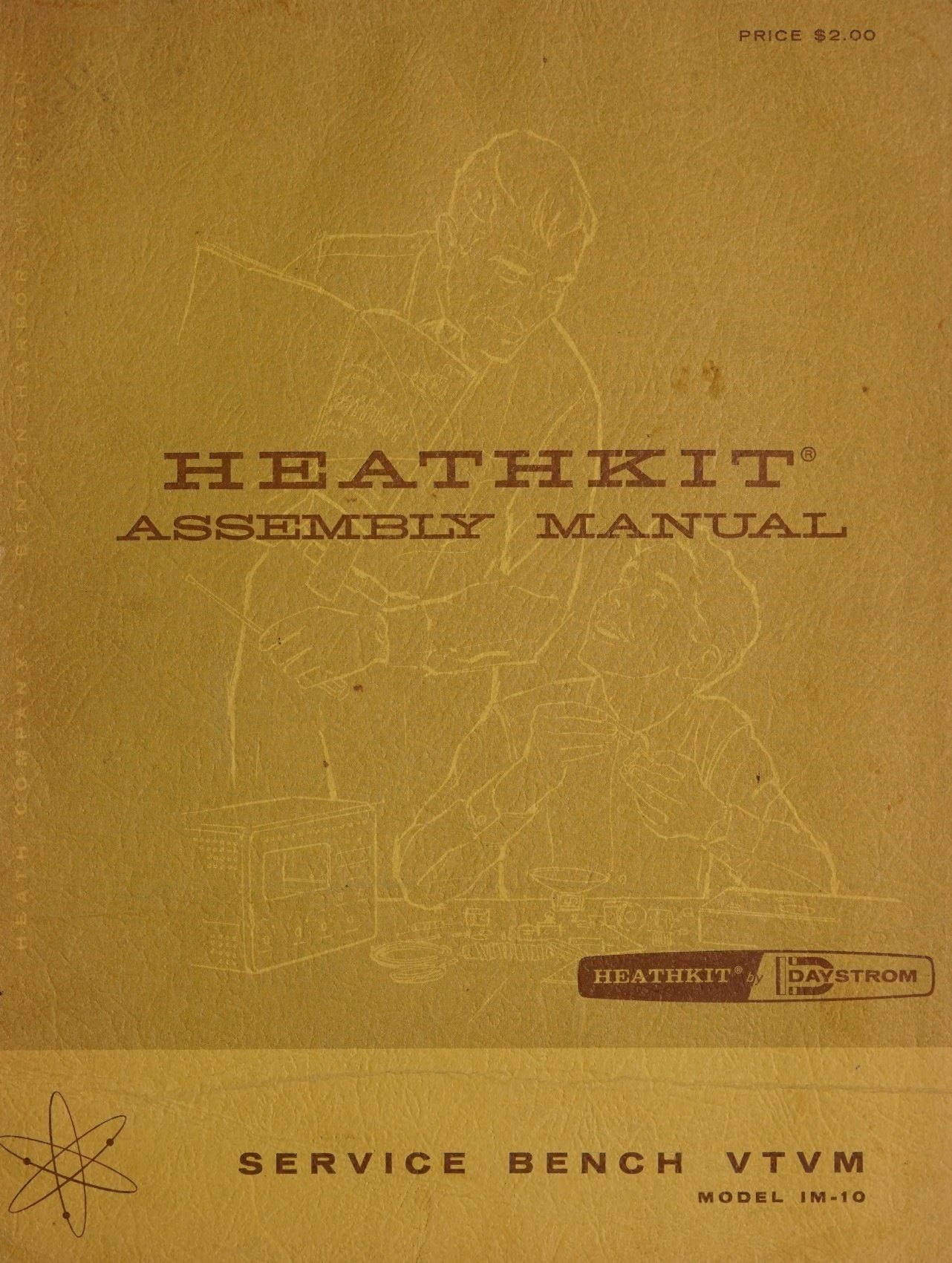
| Assembly Manual, Service Bench VTVM Model IM-10 | 595-362 | ”Copyright 1960 9/9/60” | yes, 1960 | archive.org, DLARC; schematic only |
| Assembly Manual, Vacuum Tube Voltmeter Model IM-11 | 595-486 | ”Copyright 1961”, print date 9/6/63 | yes, 1961 | archive.org, DLARC |
| …Model IM-11 (later printing) | 595-486-1 | print date 12/30/66 | not legible on scan | archive.org |
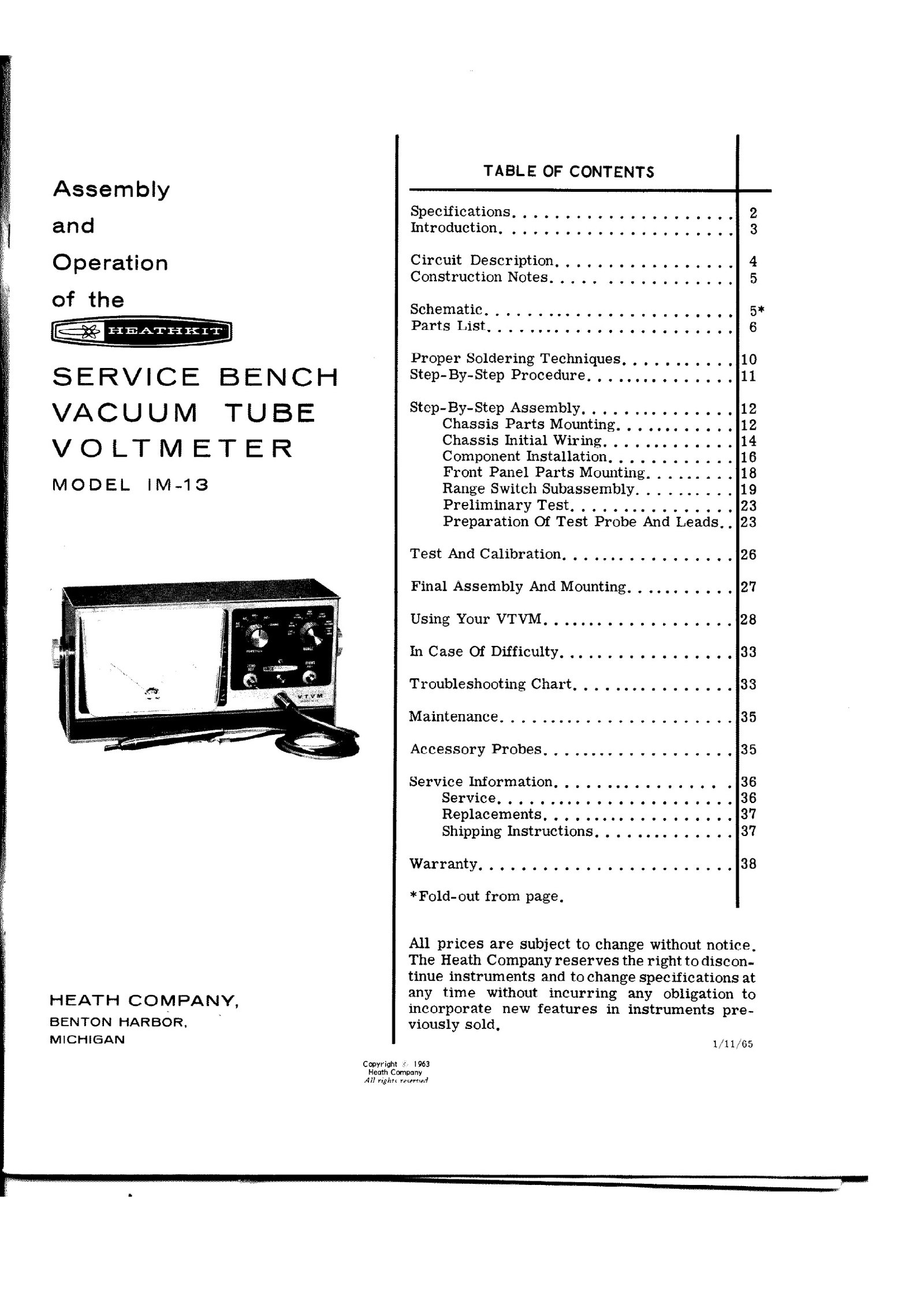
| Assembly Manual, Service Bench VTVM Model IM-13 | 595-629 | copyright line present; print date 1/11/65 | yes | archive.org |
| Assembly Manual, Vacuum Tube Voltmeter Model IM-18 | 595-1154-05 | ”Copyright © 1968” | yes, 1968 | archive.org, DLARC; partial |
| Valve Voltmeter Model IM-28U (UK/export) | not visible | — | none seen | archive.org |
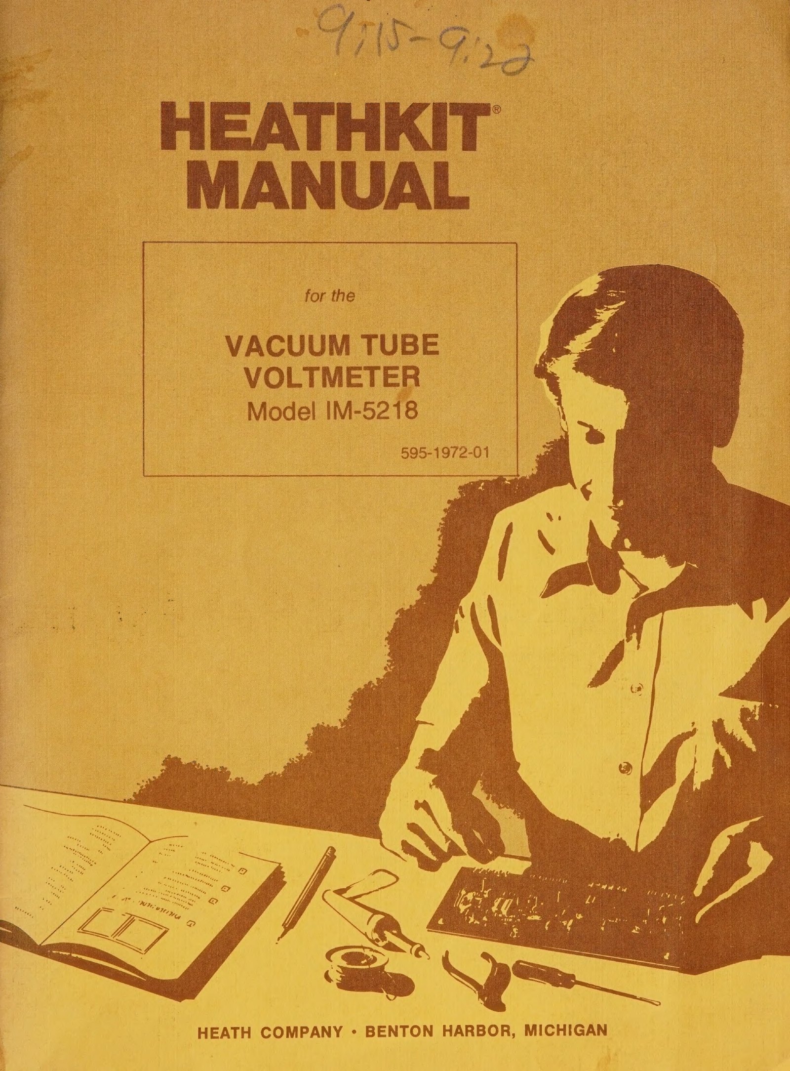
| Vacuum Tube Voltmeter Model IM-5218 | 595-1972-01 | ”Copyright © 1977” | yes, 1977 | archive.org, DLARC |
| Utility Solid-State Voltmeter Model IM-17 | 595-921-03 | manual dated 11/10/1967 in one printing | not legible on scan | archive.org |
| Solid-State Voltmeter Model IM-16 | not visible | — | none seen | archive.org |
| Science Series VTVM Model EUW-24 | not visible | — | none seen | archive.org |
No manual for an IM-32 or an IM-5228 was located online during this survey, and the V-1 and V-3 manuals appear not to survive in any public scan. The heathkitmanuals collection and the Internet Archive’s DLARC collection are the two places to check first; the DLARC scans are generally the better ones.


6.8 Catalogues consulted
Flyers and catalogues used in this dive, all at World Radio History: December 1949; January and September 1951; the 1952 catalogue; the 1954 Test Equipment catalogue; the Winter and Fall 1955 flyers; 1956; 1958 (Allied); 1959; Fall–Winter 1961; March 1962; Fall–Winter 1962–63 (the scan is filed as 1963); 1965 (800-55); 1967 (Allied); 1970 (800-03); 1972 (810-72); 1974 (810-74); Spring 1976; Fall 1978; 1980 (848); 1981 (854); 1983 (863); Fall 1985; Fall 1987; Spring 1988; Summer 1990; Winter 1991. The 1961, 1970, 1974, 1988 and 1990 scans have no text layer and were read as page images.
Further reading
- Bob Eckweiler, AF6C, “Heathkit of the Month” — the indispensable series, free for personal use. #19 V-7A and family · #110 Deluxe Service Bench VTVMs · #84 and #86 V-6 restoration · #78 IM-17 · #118 and #119 probes · index. Full schematics for the bench models are collected at w6ze.org/Heathkit/DSB.
- Brueschke, Ernest E., and Mack, Donald F., “The History of the Heath Companies”, AWA Review vol. 32 (2019). https://archive.org/details/thehistoryoftheheathcompanies — the standard company history; its V-7A board-thickness figures are internally inconsistent, as discussed in the overview volume.
- Chuck Penson, WA7ZZE, Heathkit Test Equipment Products — the reference for dating Heath test gear by cabinet style (Pre-Classic, Late Pre-Classic, Classic I, Classic II, New Look, Post New Look). Not online. https://wa7zze.com
- Rich Post, KB8TAD, “The Heathkit Legacy.” http://boatanchorpix.x10host.com/HLegacy.htm
- Heathkit Virtual Museum — pages for the V-7A and IM-11.
- Nostalgic Kits Central model matrix, useful for first and last catalogue years but with known errors in some dates. https://www.nostalgickitscentral.com/heath/products/alphabetical.html
- The Heath Company history dive on this site, for Benton Harbor, Daystrom, Schlumberger and the end of the kits.
Sources
All sources are linked inline above. The primary documents are the Heath assembly manuals held at the Internet Archive and the Heath catalogues and flyers scanned at World Radio History; the principal secondary source is Bob Eckweiler’s Heathkit of the Month series for the Orange County Amateur Radio Club.
Comments (0)