Vacuum Tube Voltmeters · Volume 3
Building the Kit
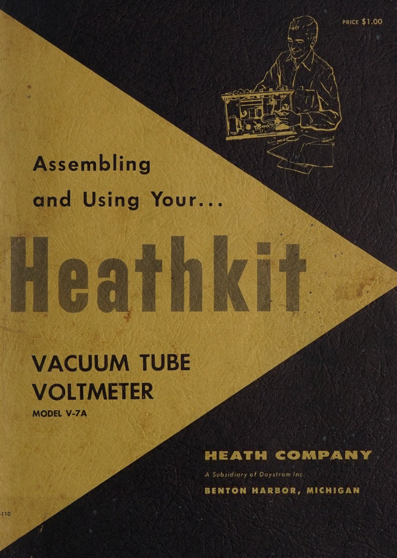
For hundreds of thousands of people the Heathkit VTVM was the first electronic instrument they ever built, and for many it was the first thing they ever soldered. It was cheap enough to risk, small enough to finish in a weekend, and useful enough afterwards to justify the outlay — Heath sold it for the same $24.50 for so long that the price became part of the advertising. The manuals survive in quantity, which makes it possible to describe the build in detail: what came in the box, the order the work was done in, which steps went wrong, and what the instrument’s assembly says about how Heath wrote instructions.
3.1 What was in the box
A VTVM kit is small. The IM-11’s parts list runs to two pages: seventeen 1 per cent precision resistors shared between the DC divider and the ohms chain, nine ordinary half-watt resistors, six capacitors, five controls, a range switch and a function switch, a 12AU7, a 6AL5, three sockets and a pilot lamp, a transformer, a rectifier, a meter, a circuit board, a cabinet, a panel, a bag of 6-32 and 4-40 hardware, an eight-wire colour-coded cable, and the parts for the test leads. Rosin-core solder came with the kit; the battery did not, on later models.
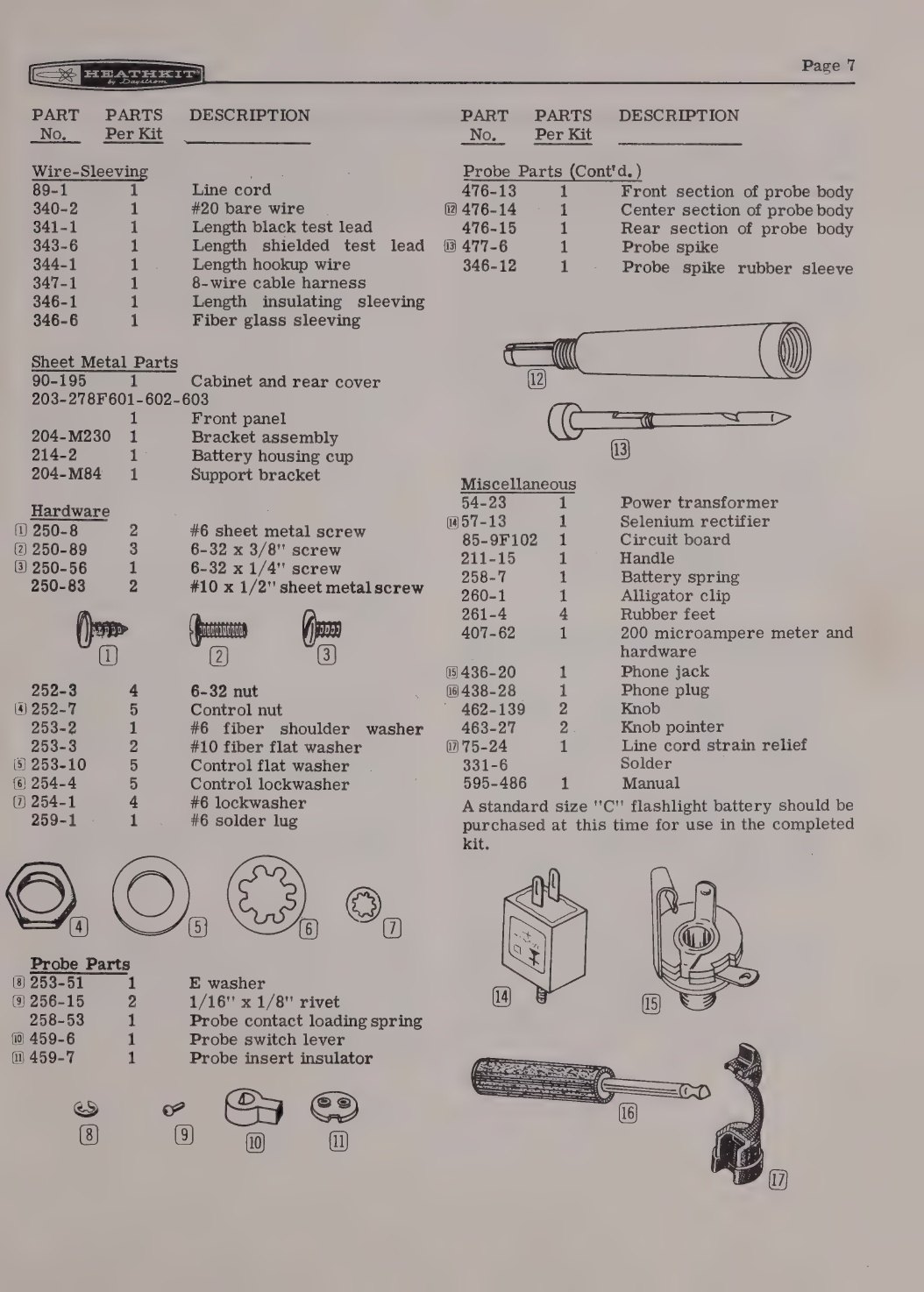
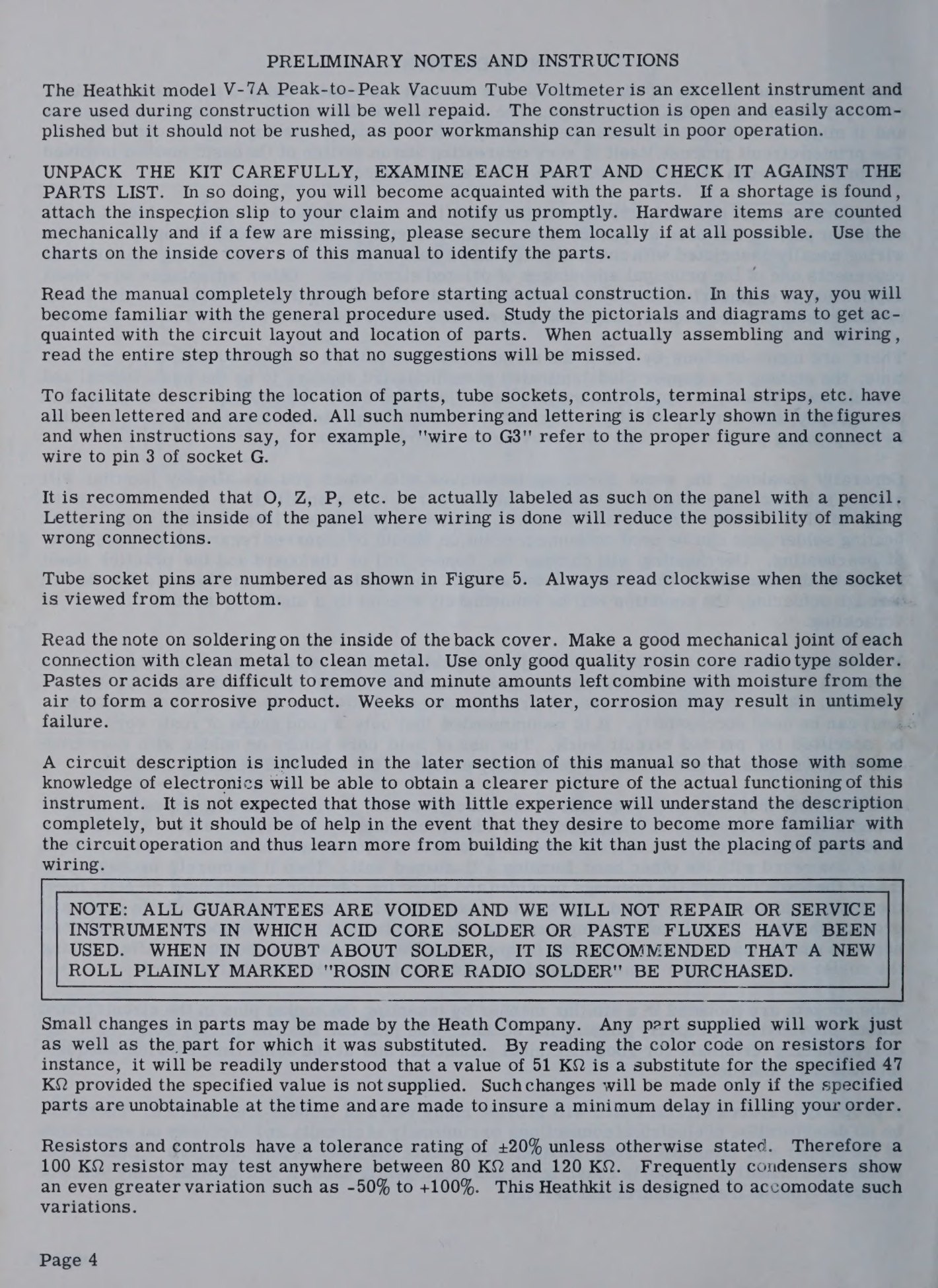
The first instruction in every manual is to unpack the kit and check every part against the list — not because parts were often missing, but because, as the manual says, in doing so “you will become acquainted with the parts”. Heath also warned that substitutions were possible and harmless: a 51 kΩ resistor might arrive where the list said 47 kΩ, and the builder was expected to read the colour code and understand why that was acceptable.
3.2 How the manual is built
The IM-11 manual’s contents page is a fair description of every Heathkit voltmeter manual from 1955 onward:
Introduction · Circuit Description · Specifications · Construction Notes · Proper Soldering Techniques · Step-By-Step Procedure · Step-By-Step Assembly (Range Switch Assembly, Front Panel Mounting, Front Panel Wiring, Circuit Board Wiring, Connecting Cable, Wiring Circuit Board To The Panel, Mounting The Battery Spring, Meter, Bracket, And Circuit Board Installation, Final Wiring) · Preliminary Test · Preparation Of Test Probe And Leads · Test And Calibration · Using Your VTVM · In Case Of Difficulty · Troubleshooting Chart · Maintenance · Accessory Probes · Service Information · Replacements · Shipping Instructions · Warranty · Schematic
Three things about that list are worth drawing out. The circuit description comes before the assembly, not after, and the manual says explicitly that a beginner is not expected to follow all of it but should read it anyway, “to learn more from building the kit than just the placing of parts and wiring”. The troubleshooting material comes with the kit rather than being sold as a service manual. And the last item is a fold-out schematic, included in a $24.50 consumer product as a matter of course.
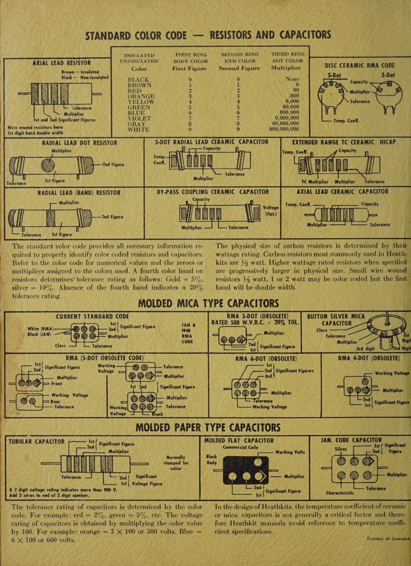
The inside covers carry the resistor and capacitor colour codes and a chart of typical component shapes, so that the one thing a beginner cannot look up is always to hand.
3.3 Soldering, and the printed circuit board
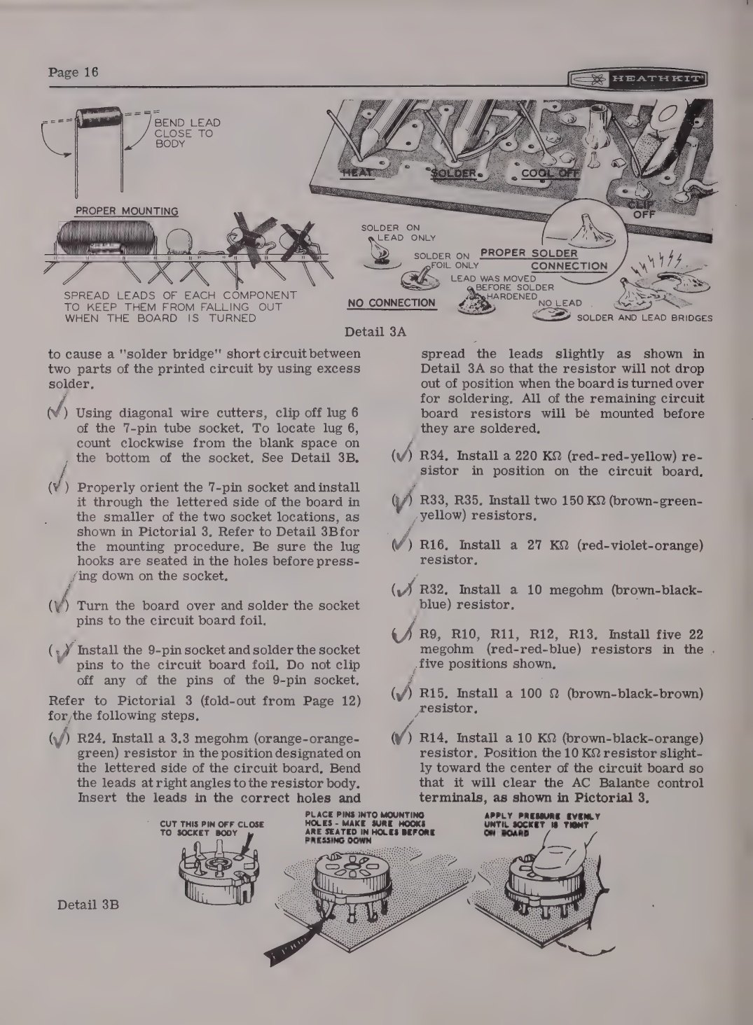
The V-7 of 1954 was the first Heathkit built on a printed circuit board, and its manual devotes a full page to explaining what one is. The explanation is careful to reassure: only the wiring pattern is printed, the components are conventional, a defective part can be removed and replaced, and the silk-screened legend on the component side identifies every part by value so that “there is no chance for error”. Mounting a resistor is described from first principles — bend both leads down into a U, push them through, splay them slightly so the part cannot fall out, solder several at a time, then trim.
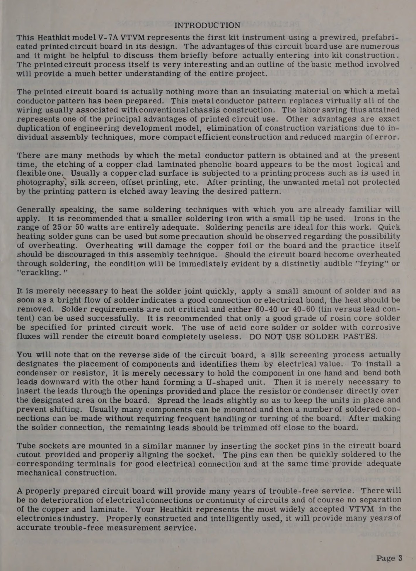
The soldering advice is specific and, for the period, unusually good. Boards want a small iron of 25 to 50 watts, or a soldering pencil; guns are permitted but discouraged, because overheating lifts the foil. Chassis and switch wiring wants a bigger iron, 60 to 100 watts, because a small one will not heat a switch lug enough for the solder to flow. Joints are to be mechanically secure before soldering, not held together by solder. Excess solder is called out as a specific hazard: it “may flow into tube socket contacts, ruining the socket, or it may creep into switch contacts and destroy their spring action.”
One instruction is set in capitals in every manual of the period, and it is the most consequential in the book. The V-7A manual supplies rosin-core solder and states plainly that using acid-core solder or paste flux voids every guarantee, and that Heath will not repair or service a kit built with either (V-7A assembly manual, 595-110).
The step notation is equally characteristic. Each step ends in (S) if the joint is to be soldered now or (NS) if another wire is still to come; in the later manuals the number of leads at the terminal is given as well, (S-2). The V-7A manual pairs each step with two boxes, one for the S/NS decision and one to tick when the step is done (Brueschke and Mack, p. 146). Builders were told to check each step off as they went, “especially if your work is interrupted”, and some marked each wire on the pictorial in coloured pencil.
3.4 The order of work
Assembly runs outside-in, and the hardest part comes first.
The range switch. All of the precision resistors mount directly on the lugs of the range switch, not on the board. The IM-11’s switch has three wafers, two of twelve lugs and one of eleven, and the manual opens with a numbering diagram and the warning that lug numbers run clockwise when the switch is viewed from the rear. Resistors are then strung between specified lugs, positioned so that their bodies sit in the space between one deck and the next without touching the shaft or the detent plate. Eckweiler’s account of the V-7A build begins the same way: “construction starts with the range switch; its numerous resistors are wired first” (Heathkit of the Month #19). A V-6 range switch, which mounts fourteen precision resistors across two decks, is hard enough to rework that Eckweiler left it assembled during a full restoration sixty years later.
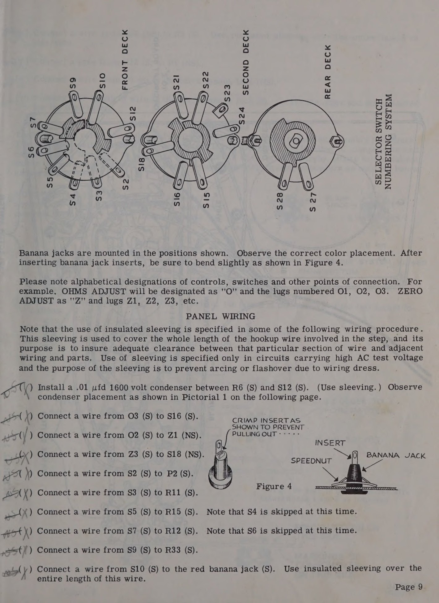
The front panel. Controls, jacks and switches are mounted next and wired to each other, with the panel lying face-down on something soft. Heath suggested pencilling the manual’s letter designations onto the inside of the panel before wiring, so that “Connect a wire to G3” could be followed without counting round the component each time.
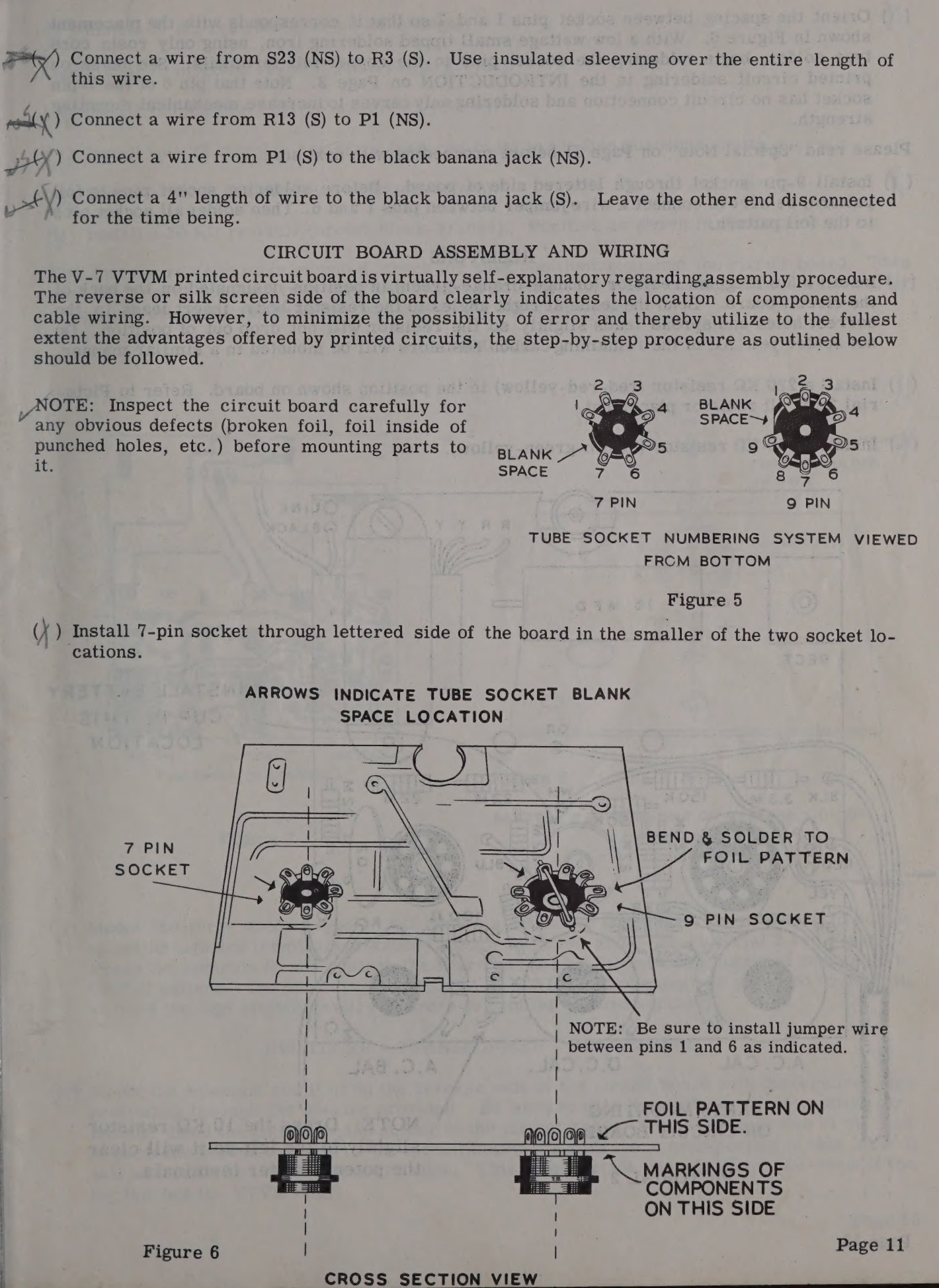
The circuit board. The board is populated with the small components, the two tube sockets, the three calibration potentiometers, the transformer and the rectifier. On the V-7 and V-7A the tube sockets are conventional miniature types whose solder lugs pass through one large hole for each socket and are bent over and soldered to the pattern — evidence, Eckweiler suggests, that Heath was either using up existing stock or could not yet buy proper board-mounting sockets.
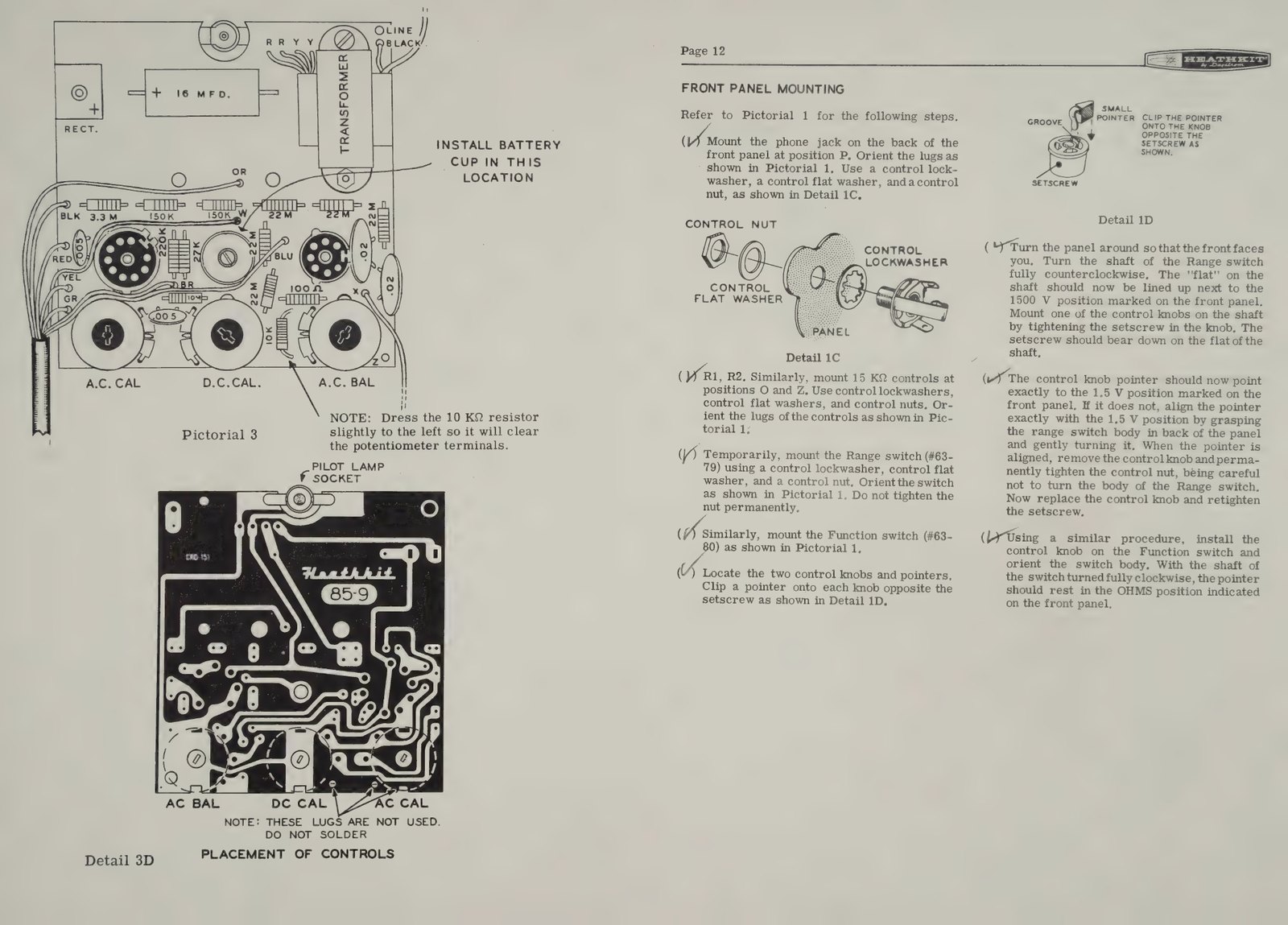
The harness. An eight-wire colour-coded cable joins the board to the panel. It arrives prefabricated; the builder strips about 3/16 inch from each end and connects the wires one at a time, which is the step most likely to produce a wrong reading later if two colours are transposed.
Mechanical assembly. A bracket carrying the battery holder, the line cord and the board is fixed to the panel by the meter’s own mounting screws, with a small Z-bracket under a third screw holding the board and one leg of the transformer. Fibre washers insulate the board from the meter studs.
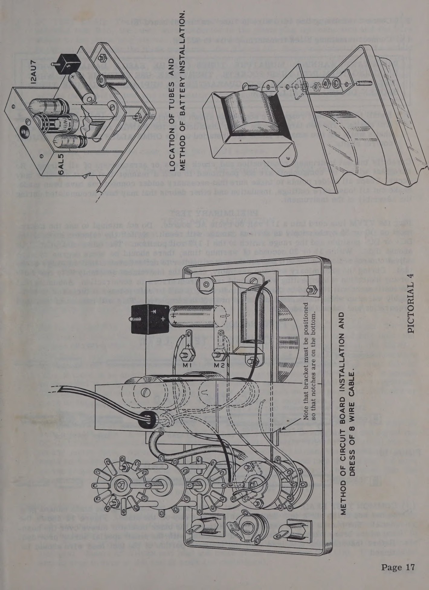
Leads, then test, then the cabinet. The test leads are made up last. Checkout, burn-in and calibration are done with the instrument out of its case; the cabinet goes on only when the instrument works (Eckweiler #19).
3.5 Tools and time
The manual’s own list is short: a screwdriver with a ¼-inch blade, a small screwdriver with a ⅛-inch blade, long-nose pliers, diagonal cutters, a knife or stripping tool, and a soldering iron. Later bench kits included a nut starter — Heath’s red plastic tool for holding a 6-32 nut in a place fingers cannot reach — and solder. The manual recommends sorting the small parts into muffin tins or egg cartons and pushing resistors and capacitors into the edge of a piece of corrugated cardboard with their values written alongside, which is still good advice.
Heath never printed an assembly time for the VTVM. What it did print was a comparison: the Winter 1955 flyer claimed the printed circuit board “cuts assembly time by one-half” against the point-to-point V-6 it replaced. For scale, the catalogues did quote times for the family’s solid-state relatives — “build the IM-17 in 3 or 4 hours” in 1972, and “you’ll be finished in just a few hours” for the IM-16 (1972 catalogue). A VTVM was an evening or two for a careful builder, and the manual’s own advice on that point is the one line of it that reads like a warning: “The construction is open and easily accomplished but it should not be rushed, as poor workmanship can result in poor operation.”
3.6 When it went wrong
Heath’s assumption was that a proportion of builders would get into trouble, and the back of the manual is organised around that assumption rather than around returns.
A builder who ruined the board — most often by using acid-core solder, the one thing the manual forbids in capitals — could buy a circuit board repair kit. The V-7A’s, part R-V-7A at $3.00, contained a new board, both tube sockets and every board-mounted resistor and disc ceramic capacitor; the manual notes that the rectifier, battery cup, controls, filter capacitor and transformer “can be salvaged with little difficulty”. A replacement range switch was $2.25 and a selector switch $2.00 — against a complete kit at $24.50.
Free technical consultation came with the kit. The Technical Consultation Department existed, the manual says, “to provide assistance for those who encounter difficulty in the construction, operation or maintenance of Heathkit equipment”, explicitly not as a general technical help desk and not for modifications. A finished instrument could be sent to Benton Harbor or, later, to any Heathkit Electronic Center for service; the manual’s shipping instructions are emphatic that the original kit carton is not adequate packing for an assembled instrument, and specify a rugged container with at least three inches of shredded newspaper on every side.
The warranty itself was ninety days, and its wording is worth reading as a statement of the company’s position: Heath warranted that its products, “when correctly assembled, calibrated, adjusted, and used in accordance with our printed instructions, will meet published specifications”, and undertook to replace defective parts free and pay the shipping “anywhere in the world”. It excluded, equally plainly, damage caused by corrosive solder, defective tools, incorrect assembly, misuse and customer modifications. The builder’s work was his own risk; the parts and the instructions were Heath’s.
3.7 The kit as a course
From 1961 Heath sold the instrument bundled with a textbook. The EF-1 “How To Understand and Use Your Vacuum Tube Voltmeter”, the first title in the Heathkit Technical Application Series, came with everything needed for its experiments except the meter itself, and included a small power-supply kit built as part of the course. Its syllabus ran from electron flow and Ohm’s law through VOM theory and triodes to alignment and television servicing, and the catalogue offered the combination as EF-1-3 with an IM-11 for $32.50, or as EF-1-6 with an IM-28 for $49.95 (Fall–Winter 1961 catalogue; 1962–63 catalogue; 1970 catalogue). The pairing says something about how Heath saw the instrument: not as a component of a workshop but as the beginning of one.
Sources
- Heathkit Assembly Manual, Vacuum Tube Voltmeter Model V-7A (595-110). Internet Archive. https://archive.org/details/heathkitmanualva00unse
- Heathkit Assembly Manual, Vacuum Tube Voltmeter Model V-7 (595-90). Internet Archive. https://archive.org/details/manualsplus_08096
- Heathkit Assembly Manual, Vacuum Tube Voltmeter Model IM-11 (595-486). Internet Archive. https://archive.org/details/heathkitassembly00unse_7
- Heathkit Assembly Manual, Vacuum Tube Voltmeter Model IM-18 (595-1154). Internet Archive. https://archive.org/details/heathkitassembly00unse_4
- Eckweiler, Bob (AF6C). “Heathkit of the Month #19: V-7A VTVM.” https://www.w6ze.org/Heathkit/Heathkit_019_V7a.pdf
- Eckweiler, Bob (AF6C). “Heath of the Month #86: V-6 VTVM Restoration, part II.” https://www.w6ze.org/Heathkit/Heathkit_086_V6RebuildII.pdf
- Brueschke, Ernest E., and Mack, Donald F. “The History of the Heath Companies.” AWA Review vol. 32 (2019). https://archive.org/details/thehistoryoftheheathcompanies
- Heath Company catalogues and flyers, World Radio History. https://www.worldradiohistory.com/Archive-Catalogs/Heathkit_Catalogs.htm
Comments (0)